


TRACER 6000 Series Integrated System Manual Section 3 Engineering Guidelines
612806420L1-1F Copyright © 2005 ADTRAN, Inc. 33
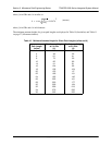
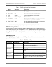
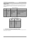
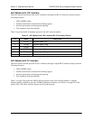
CRAFT Port (DB-9)
The CRAFT connector provides a female DB-9 terminal connection (wired as a DCE interface), used for
terminal access to the TRACER system. Table 4 shows the pinout. A null modem cable is necessary for
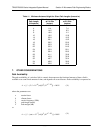
connecting the
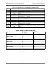
CRAFT port to a modem for remote dial-up access. Table 5 shows the pinout for a null
modem cable.
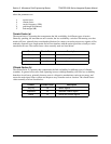
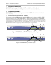
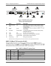
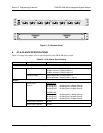
4. REVIEWING THE TRACER 64X0 REAR PANEL DESIGN
Figure 3 on page 34 identifies the features of the TRACER rear panel, and Table 6 on page 34 provides a
brief description of each interface.
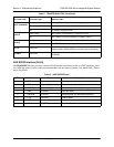
Table 4. CRAFT Pinout
Pin
Name
Source Description
1CD
TRACER Carrier detect
2RXDATA
TRACER Received data (to attached equipment)
3 TXDATA Attached Equipment Transmit data (from attached equipment)
4 DTR Attached Equipment Data terminal ready (unused)
5 GND Common Signal ground
6DSR
TRACER Data set ready
7 RTS Attached Equipment Request to send (unused)
8CTS
TRACER Clear to send
9RI
TRACER Ring indicator (unused)
Table 5. Null-Modem Pinout
Modem
Pin
TRACER 64x0
Pin
1 (CD) Unconnected
2 (RXD) 3 (TXD)
3 (TXD) 2 (RXD)
4 (DTR) 6 (DSR)
5 (GND) 5 (GND)
6 (DSR) 4 (DTR)
7 (RTS) 8 (CTS)
8 (CTS) 7 (RTS)
9 (RI) Unconnected