


Section 5 User Interface Guide TRACER 6000 Series Integrated System Manual
86 Copyright © 2005 ADTRAN, Inc. 612806420L1-1F
> RF LINK MANAGEMENT BRIDGE CONFIGURATION
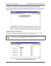
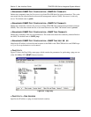
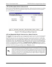
Figure 34 shows the RF Link Bridge Configuration menu page, which contains the parameters for enabling
and configuring the TRACER 64x0 management bridge for passing information from the management
port across the RF link to the remote end.
Figure 34. RF Link Management Bridge Configuration
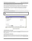
>RF LINK MANAGEMENT BRIDGE CONFIGURATION > BRIDGE OPERATION
The TRACER 64x0 has the capability to pass management information received on the local management
port (
MGMT) across the RF link to the remote end. This feature allows units to operate in a daisy-chain
fashion, providing the user with configuration, management, and monitoring functions for all TRACER
systems in the chain as well as any other Ethernet-capable device located on the same network segment as
the TRACER systems. The TRACER 64x0 takes Ethernet traffic received on the local management port
and determines (using a MAC bridge functionality) whether the traffic is intended for the local TRACER
system or a system located over the RF link. If the
BRIDGE OPERATION is ENABLED and Ethernet traffic is
received on the MGMT interface for a remote TRACER system, the TRACER 64x0 bridges the data over
the RF link. The RF Link Management Bridge feature is
ENABLED by default.
The RF Link Management Bridge feature should be used only to pass TRACER
management information from one TRACER to another over the RF link. It is important to
employ an IP addressing scheme that allows for independent networks at the local and all
remote sites in the daisy-chain because the TRACER 64x0 will bridge all Ethernet traffic
bound for a remote network over the RF link. Excessive bridge traffic can impede proper
management operation; it is recommended that bridge traffic be limited to configuration,
management, and monitoring functions.