


TRACER 6000 Series Integrated System Manual Section 3 Engineering Guidelines
612806420L1-1F Copyright © 2005 ADTRAN, Inc. 35
DC Power Connection (Plug-In Terminal Block)
The TRACER 64x0 can operate from a supply between 21 and 60 VDC, with either polarity referenced to
ground, and consumes less than 25 W. Power supplies should be able to provide up to 25 W at the selected
voltage. Current required (in amps) is determined by dividing the power consumed (in watts) by the applied
voltage (in volts). For example, at 48 V, TRACER 64x0 would draw approximately 0.52 A
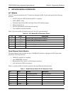
(25 W/48 V). Table 8 shows the DC power connection pinout.
Fuse
The fuse holder, accessible from the rear panel of the TRACER 64x0, accepts a generic 2 A, 250 V, 2-inch
slow-blo fuse.
Alarm Contacts (Plug-In Terminal Block)
An RF link down condition is indicated with both normally open (NO) and normally closed (NC) alarm
contacts on the rear panel of the TRACER 64x0 system. In normal operation, the NC contact is electrically
connected to the common contact (COM) and the NO contact is isolated. When the RF link drops, the NC
contact becomes isolated and the NO is electrically connected to COM. This allows RF down conditions to
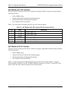
be reported to external alarm monitoring systems. Table 9 provides the alarm contact pinout.
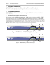
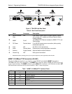
Antenna Interface (N-Type Connector)
The ANTENNA interface (N-type connector) connects to the customer-supplied antenna using standard
antenna feedline cable. When determining the cable specifications for your application, refer to Section 2,
Microwave Path Engineering Basics (System Losses (L) on page 21) for a discussion on cable length and
Applying power to the radio without a 50
Ω
load attached to the antenna interface can
damage the system. Verify the 50
Ω
load is attached before powering the radio.
When using a power source that has the positive terminal or the negative terminal
connected to earth ground, the grounded terminal must be attached to the TRACER 64x0
power input that is identified with the ground symbol. Otherwise, equipment damage will
occur. When using a power source that has neither terminal connected with earth ground
(floating), either terminal may be connected to the TRACER 64x0 power input identified
with the ground symbol.
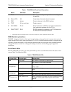
Table 8. DC Power Connector Pinout
Pin Name Description
1 +/– Voltage
2 GND Ground
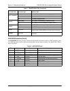
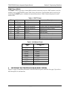
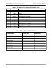
Table 9. Alarm Contact Connector Pinout
Pin Name Description
1 COM Common Contact
2 NO Normally-Open Contact
3 NC Normally-Closed Contact