


Section 5 User Interface Guide TRACER 6000 Series Integrated System Manual
76 Copyright © 2005 ADTRAN, Inc. 612806420L1-1F
> T1X STATUS/CONFIGURATION/LOOPBACK > LOOP/NORMAL STATE > NORMAL
Defines the T1 link as normal data transport mode; there are no active loopbacks.
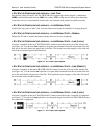
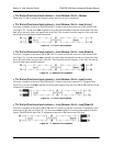
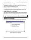
> T1X STATUS/CONFIGURATION/LOOPBACK > LOOP/NORMAL STATE > LINK [LOCAL]
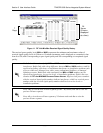
Activates a loopback at the local TRACER 64x0 T1 framer towards the remote end of the wireless link
(see Figure 22). Use the local
LINK loopback to loop the data transmitted from the remote end of the link
back across the radio link to the remote end of the link. This loopback tests the integrity of the radio link
and all the associated digital and RF hardware.
Figure 22. T1 Local Link Loopback
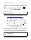
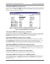
> T1X STATUS/CONFIGURATION/LOOPBACK > LOOP/NORMAL STATE > LINK [REMOTE]
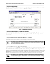
Activates a loopback at the remote TRACER 64x0 T1 framer towards the local end of the wireless link
(see Figure 23). Use the remote
LINK loopback to loop the data transmitted from the local end of the link
across the radio link to the local end of the link. This loopback tests the integrity of the radio link and all
the associated digital and RF hardware.
Figure 23. T1 Remote Link Loopback
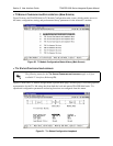
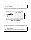
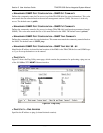
> T1X STATUS/CONFIGURATION/LOOPBACK > LOOP/NORMAL STATE > LINE [LOCAL]
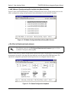
Activates a loopback at the local TRACER 64x0 T1 framer towards the connected T1 equipment (see
Figure 24). Use the local
LINE loopback to test data path integrity from the local TRACER 64x0 unit to the
connected T1 equipment.
Figure 24. T1 Local Line Loopback
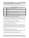
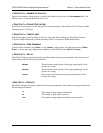
> T1X STATUS/CONFIGURATION/LOOPBACK > LOOP/NORMAL STATE > LINE [REMOTE]
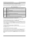
Activates a loopback at the remote TRACER 64x0 T1 framer towards the connected T1 equipment at the
remote end of the link (see Figure 25). Use the remote
LINE loopback to test data path integrity from the
remote TRACER 64x0 unit to the T1 equipment connected at the remote end of the link.
Figure 25. T1 Remote Line Loopback