


TRACER 6000 Series Integrated System Manual Section 5 User Interface Guide
612806420L1-1F Copyright © 2005 ADTRAN, Inc. 87
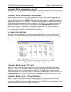
>RF LINK MANAGEMENT BRIDGE CONFIGURATION > INACTIVITY TIMEOUT
Defines the amount of time that an Ethernet address is maintained in the bridge table. A shorter time
produces a more dynamic bridge table, allowing addresses to change network segments without causing
extra forwarded traffic. A longer time reduces the amount of unnecessarily forwarded traffic (due to
unknown Ethernet addresses), but causes the bridge table to respond more slowly to a MAC address
switching network segments. Valid choices are:
5 SEC (default), 15 SEC, 30 SEC, 1 MIN, and 5 MIN.
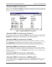
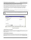
> SYSTEM ALARMS
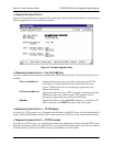
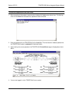
Figure 35 shows the System Alarms menu page, which displays system alarm information for the link, fans,
and temperature of the local and remote systems.
Figure 35. System Alarms
> SYSTEM ALARMS > LINK ALARM
Indicates the current status of the RF link between the local and remote TRACER 64x0 high power systems.
LINK UP indicates that the system detects a valid RF link and LINK DOWN indicates that the system does not
detect a valid RF link.
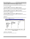
> SYSTEM ALARMS > FAN ALARMS
Displays operational alarms for the system fans. An alarm is indicated when the system detects that the
fan(s) rotational speed is below nominal operation and when the fan(s) is not functioning properly. A
FAN
S
PEED ALARM could indicate a physical blockage or an intermittent fan problem. The FAN SPEED ALARM
System Alarm information is only available for the TRACER 64x0 high power systems.