


Workgroup Remote Access Switch 115
C
ONFIGURING
B
ASIC
IP R
OUTING
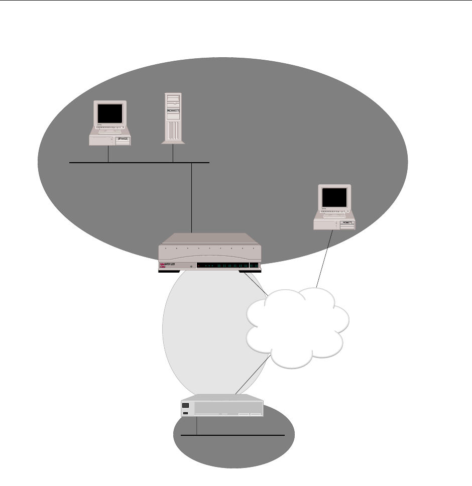
IP Network Interfaces
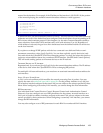
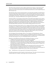
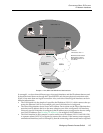
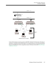
In example 1, we show three different types of network interfaces and the IP subnets that are used.
It should be noted that even though the CyberSWITCH only has one physical connection to the
WAN, it has more than one logical connection. Also, each one of these logical interfaces can be in
different subnetworks.
• The LAN interface is the simplest. It specifies the IP address (128.1.1.1) which connects the sys-
tem to the Ethernet LAN. In our example, only one LAN interface is configured.
• The Direct Host interface doesn’t have an IP address. Devices that use the Direct Host interface
must have an IP address that is on the same subnet as one of the configured LAN interfaces.
Since only one LAN interface is configured, that IP address must correspond to the one config-
ured LAN IP address. (See Secondary IP Addressing for multiple LAN IP addresses).
• The WAN interface in this example is used to connect two IP subnets (128.1.1.0 and 198.1.2.0).
A separate subnet (192.2.2.0) is required to connect the subnets. If the remote router supports
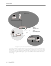
unnumbered interfaces (such as Example 2), then the connecting subnet would not be required.
ISDN
Host
File
Server
Host
Router
128.1.1.8 128.1.1.3
Subnet 128.1.1.0
(128.1.1.2 uses WAN Direct Host Interface)
128.1.1.2
Interfaces:
LAN Interface 128.1.1.1
WAN Direct Host Interface
WAN Interface 192.2.2.1
both WAN Interfaces use
one PRI line
198.1.2.3
Subnet 198.1.2.0
(Uses WAN Interface)
192.2.2.1
Subnet 192.2.2.0
Needed for
WAN Interface
128.1.1.1
192.2.2.3
Example 1: LAN, WAN and WAN Direct Host Interfaces
POWER
SERVICE
TX
RX
10BASE - T
LAN B-CHANNELS E1 ONLY
B2 B4
B6 B8
B26 B28
B22 B24
B18 B20
B14 B16
B10 B12
B30 L1
B1 B3
B5 B7
B25 B27
B21 B23
B17 B19
B13 B15
B9 B11
B29 B31
E1
D
T1
D