


USER’S GUIDE
216 CyberSWITCH
-- the rate at which data frames may be sent into the network without incurring congestion. This is
generally accepted as the end-to-end available bandwidth at which frame relay service devices may
enjoy sustained frame transmission. By definition this must be less than the throughput that the
actual physical access link can support. However, for short periods of time, service devices may
exceed this rate by defined values. This excess is known as the excess information rate and is
defined as the bandwidth available above and beyond the committed rate. The reason this is
possible is because statistically, not each PVC within the access will make use of its complete
bandwidth allocation. Busy PVCs may essentially borrow bandwidth from underutilized PVCs.
The Frame Relay software has the capability to transmit data above the committed information rate
up to the excess information rate. Note that the sum of the committed and the excess information
rates must not exceed the rate defined by the physical link. These rates are user-configurable
options.
C
ONGESTION CONTROL OVERVIEW
Congestion occurs when traffic arriving at a resource, whether network or user equipment, exceeds
that node’s capacity. Congestion notification in the device plane is used to inform the equipment
(at the ingress point to the network) of the congestion, and allows the user equipment to initiate
congestion avoidance procedures. The intent is to reduce the negative effects on both network and
user equipment: the user equipment should take corrective action to reduce the congestion, or to
notify the source that throughput has been exceeded. Congestion control is very important in
providing reliable frame relay services. Congestion can be detected in two ways, implicitly and
explicitly. Implicit indications are provided by lost frames whereas explicit congestion indications
are provided for within the frame relay protocol.
C
URRENT RESTRICTIONS
Currently, only PVC (Permanent Virtual Circuit) frame relay connections are implemented.
Through configuration, PVC connections establish a permanent association between two DTEs.
The only types of facilities to be supported for frame relay access are channeled interfaces such as
T1 and BRI. However, currently only 1 port per channeled interface is supported until SVC
standards are available.
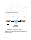
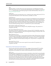
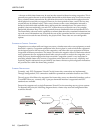
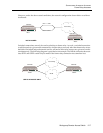
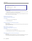
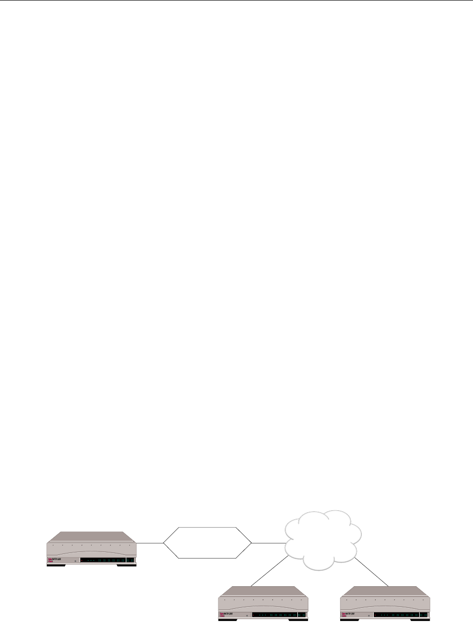
Frame relay supports only a single Permanent Virtual Circuit connecting any two given systems.
To illustrate this point, the following diagram shows a frame relay network configuration that
would be allowed:
"SITE1"
"SITE2" "SITE3"
DLCI 1 -> NE2
DLCI 2 ->NE 3
ALLOWED
Frame Relay
POWER
SERVICE
TX
RX
10BASE - T
LAN B-CHANNELS E1 ONLY
B2 B4
B6 B8
B26 B28
B22 B24
B18 B20
B14 B16
B10 B12
B30 L1
B1 B3
B5 B7
B25 B27
B21 B23
B17 B19
B13 B15
B9 B11
B29 B31
E1
D
T1
D
POWER
SERVICE
TX
RX
10BASE - T
LAN B-CHANNELS E1 ONLY
B2 B4
B6 B8
B26 B28
B22 B24
B18 B20
B14 B16
B10 B12
B30 L1
B1 B3
B5 B7
B25 B27
B21 B23
B17 B19
B13 B15
B9 B11
B29 B31
E1
D
T1
D
POWER
SERVICE
TX
RX
10BASE - T
LAN B-CHANNELS E1 ONLY
B2 B4
B6 B8
B26 B28
B22 B24
B18 B20
B14 B16
B10 B12
B30 L1
B1 B3
B5 B7
B25 B27
B21 B23
B17 B19
B13 B15
B9 B11
B29 B31
E1
D
T1
D
CSX1200
CSX1200 CSX1200