


USER’S GUIDE
38 CyberSWITCH
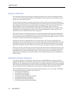
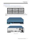
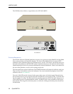
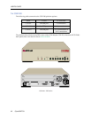
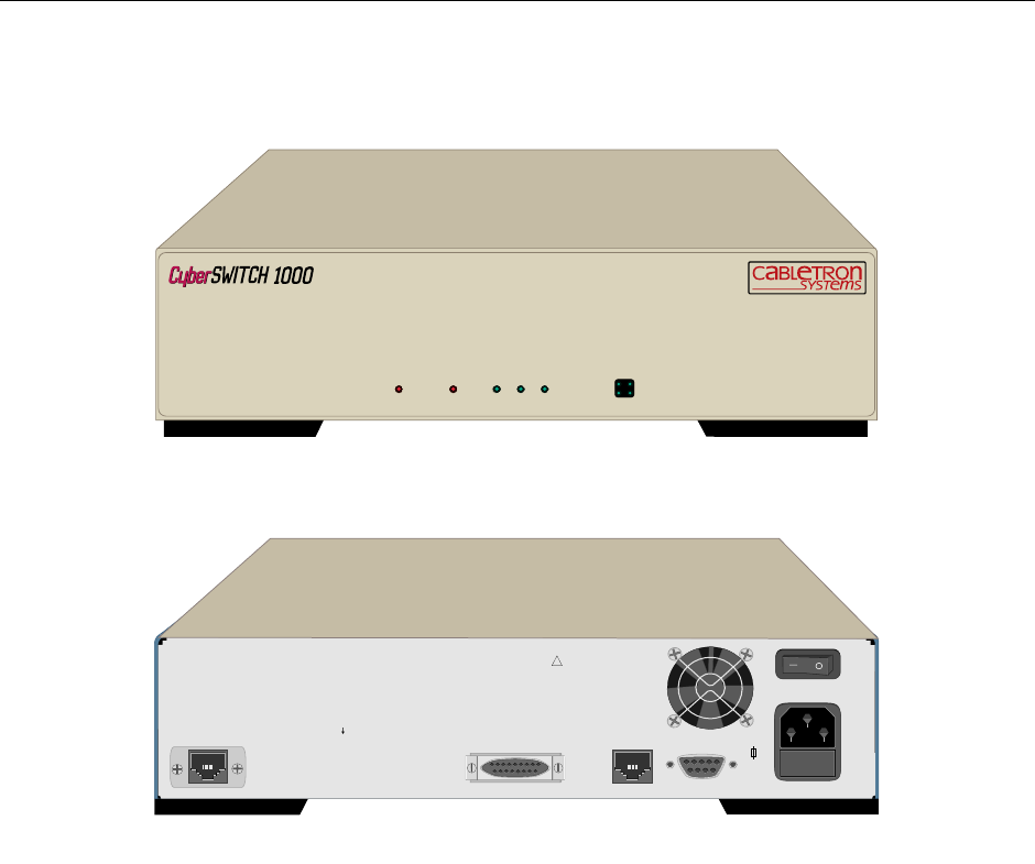
The CSX1001, shown below, is equivalent to the NE Link 1000 B2.
P
LATFORM DESCRIPTION
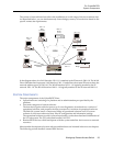
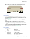
The NE Link 1000 and CSX1000 platforms consists of two processors (the 80386 EX and the 80960
SA), system memory, and interface adapters. The front of the platforms have a series of LED
indicators. These indicators light up to indicate power, service, LAN access, and WAN access. On
the back of the platform is the ON/OFF switch, connectors for power, the LAN, the WAN, and an
administration port for local or remote administration console attachment. There is a fan housed in
the rear of the platform, as well as side venting on the unit.
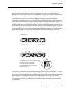
The front panel has a series of indicators. The POWER indicator will remain lit while the unit is on.
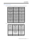
There are also LAN, WAN, and service indicators. For a more detailed description of each LED
indicator, refer to LED Indicators.
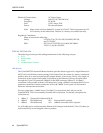
The unit’s ON/OFF switch is located in the upper right corner of the back panel. Directly below
this switch are the AC power input and fuse box. Note that the unit requires a 250V, 5 x 20 mm time-
lag fuse rated at 1.6 amps. The back panel also provides connectors for WAN and LAN access, as
well an RS232 port for an administration console. The RS232 port is also available for PPP-Async
data transfer. The fan grill on the back panel, as well as the venting on the side panel, should not
be obstructed.
BRI (Termination switches behind plate; see diagram
FUSE TYPE: IEC 127/ III RATED F1.6AL-250V
INPUT
85-250V 47-63 - 1.6A MAX
CONSOLE
10Base-T
AUI
CAUTION
FOR CONTINUED PROTECTION
AGAINST RISK OF FIRE,
REPLACE
ONLY WITH SAME TYPE AND
RATING OF FUSE.
!
The CSX1001
WORKGROUP REMOTE ACCESS SWITCH
LAN
10BASE-TRXTXSERVICE
CH-2
D-CH
CH-1
SYNC
POWER
LINE
1
AGI