


Workgroup Remote Access Switch 117
C
ONFIGURING
B
ASIC
IP R
OUTING
IP Network Interfaces
IP RIP AND THE IP NETWORK INTERFACES
Routing Information Protocol (RIP) is a protocol used to exchange routing information among IP
devices. Using IP RIP can automate the maintenance of routing tables on IP devices and relieve you
of having to keep the routing tables up to date manually. IP RIP determines the shortest path
between two points on a network in terms of the number of “hops” between those points.
LAN type interfaces (LAN and RLAN Interfaces) and WAN interfaces are used by devices to
advertise the IP RIP information. The type of interface used for IP RIP depends on the network
configuration. Different interface information must be configured depending on the type of
interface used to propagate the IP RIP information.
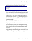
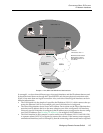
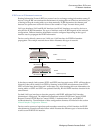
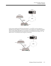
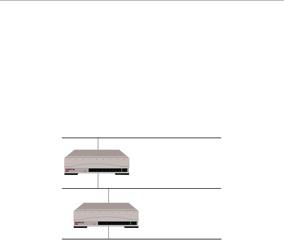
Devices used to directly connect two LANs use a LAN interface for IP RIP information
propagation. The example network shown below illustrates this type of network.
In the above example, both systems (SITE1 and SITE2) need no static routes. SITE1 will learn about
Network 3 that can be reached via SITE2 by listening to the IP RIP advertisements from SITE2.
SITE2 will also learn about Network 1 in the same way. After learning this route information, the
routing tables on SITE1 and SITE2 are updated. Basically, RLAN IP RIP interfaces function in the
same manner.
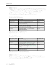
For both LAN type interfaces to function properly with IP RIP, additional LAN interface
information is configured. The additional information includes: IP RIP Send Control, IP RIP
Respond Control, IP RIP Receive Control, IP RIP v2 Authentication Type, and IP RIP v2
Authentication key. The definitions of these configuration elements are included in the section
Network Interface Configuration Elements.
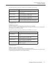
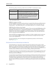
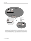
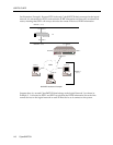
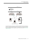
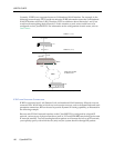
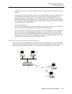
Devices used to connect a logical network to another network use a WAN interface for IP RIP
advertisements. Example networks follow which illustrate the different types of networks that
would use an IP RIP WAN interface.
Network 1 (1.0.0.0)
Network 3 (3.0.0.0)
Network 2 (2.0.0.0)
LAN Interface 1 1.0.0.1
LAN Interface 2 2.0.0.1
LAN Interface 3 2.0.0.2
LAN Interface 4 3.0.0.2
"SITE1"
"SITE2"
POWER
SERVICE
TX
RX
10BASE - T
LAN B-CHANNELS E1 ONLY
B2 B4
B6 B8
B26 B28
B22 B24
B18 B20
B14 B16
B10 B12
B30 L1
B1 B3
B5 B7
B25 B27
B21 B23
B17 B19
B13 B15
B9 B11
B29 B31
E1
D
T1
D
POWER
SERVICE
TX
RX
10BASE - T
LAN B-CHANNELS E1 ONLY
B2 B4
B6 B8
B26 B28
B22 B24
B18 B20
B14 B16
B10 B12
B30 L1
B1 B3
B5 B7
B25 B27
B21 B23
B17 B19
B13 B15
B9 B11
B29 B31
E1
D
T1
D