


Send documentation comments to mdsfeedback-doc@cisco.com
A-8
Cisco MDS 9200 Series Hardware Installation Guide
OL-17468-02
Appendix A Cabinet and Rack Installation
Cisco MDS 9000 Family telco and EIA Shelf Bracket
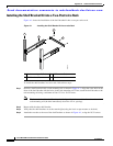
Step 4 Attach the crossbar to the shelf brackets as shown in Figure A-2, using the 10-32 screws.
Step 5 Insert the slider rails into the shelf brackets as shown in Figure A-2. Then, attach them to the rear
rack-mounting rails using a minimum of four 12-24 or 10-24 screws.
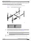
Installing the Switch on the Shelf Brackets
This section provides general instructions for installing the switch on top of the shelf brackets. For
installation instructions, see the “Installing the Chassis in a Cabinet or Rack” section on page 2-5.
Warning
This unit is intended for installation in restricted access areas. A restricted access area can be
accessed only through the use of a special tool, lock and key, or other means of security.
Statement 1017
Warning
Only trained and qualified personnel should be allowed to install, replace, or service
this equipment.
Statement 1030
Note Before you install, operate, or service the system, refer to the Regulatory Compliance and Safety
Information for the Cisco MDS 9000 Family for important safety information.
To install the switch on top of the shelf brackets, follow these steps:
Step 1 Ensure that the shelf brackets are level and securely attached to the rack-mounting rails, the crossbar is
securely attached to the shelf brackets, and the rack is stabilized.
Step 2 Slide the switch onto the shelf brackets, ensuring it is squarely positioned.
Step 3 Attach the switch to the rack-mounting rails. See the “Installing the Chassis in a Cabinet or Rack”
section on page 2-5.
Caution We recommend grounding the chassis, even if the rack is already grounded. There is a
grounding pad with two threaded M4 holes on the chassis for attaching a grounding lug.