


Send documentation comments to mdsfeedback-doc@cisco.com
Index
IN-3
Cisco MDS 9200 Series Hardware Installation Guide
OL-17468-02
Fiber Connectivity 1-21
fiber optic cables
maintaining
3-13
Fibre Channel/Gigabit Ethernet SFP transceivers 1-37
Fibre Channel ports
connecting
3-6
connecting with LC-type cable (figure) 3-12
Figure 1-8 1-13
G
Generation 1 modules 1-12
Generation 2 modules 1-12
Gigabit Ethernet/Fibre Channel SFP transceiver
specifications
B-15
grounding
attaching the ESD wrist strap
2-21
best practices 2-19
chassis 2-24
chassis (figure) 2-25
establishing the system ground 2-23
tools and equipment 2-23
H
heat dissipation specifications B-5
I
IBM BladeCenter 1-5
installing
equipment required
2-4
rack-mount (front-facing) 2-6
rack-mount (rear-facing) 2-16
rack-mount (rotated brackets) 2-14
rack-mount front-facing (figure) 2-9
rack-mount rear-facing (figure) 2-17
SFP transceiver cables 3-11
SFP transceivers (note) 3-10
X2 transceivers 3-8
interface module
description
1-10
figure 1-10
LEDs (table) 1-11
IPS modules
description
1-25
IPS-4 (figure) 1-26
IPS-8 (figure) 1-26
LEDs (table) 1-27
power and heat specification B-5
IP Storage Services modules. See IPS modules
IPv6
1-21
L
LC-type cables
connecting to Fibre Channel ports
3-12
figure 3-12
LEDs
ASM (table)
1-31
CSM (table) 1-34
fan module 1-36
interface module (table) 1-11
IPS modules (table) 1-27
MPS-14/2 (table) 1-25
supervisor module (table) 1-9
switching modules (table) 1-17, 1-20
M
maintaining
fiber optic cables
3-13
SFP transceivers 3-13
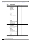
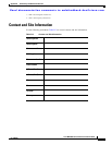
maintenance records D-1
MGMT 10/100/1000 Ethernet port
cabling
C-4
pinouts C-4