


Send documentation comments to mdsfeedback-doc@cisco.com
2-34
Cisco MDS 9200 Series Hardware Installation Guide
OL-17468-02
Chapter 2 Installing the Cisco MDS 9200 Series
Removing and Installing Components
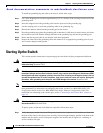
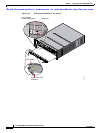
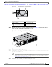
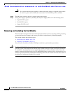
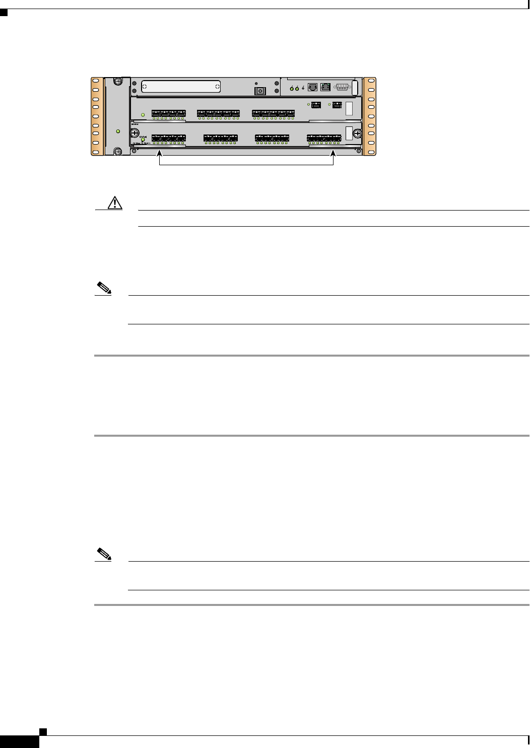
Figure 2-20 Closing the Ejector Levers
Caution Do not press down too forcefully on the levers because they can bend.
d. Press down and simultaneously close the left and right ejector levers to fully seat the module in the
backplane connector. The ejector levers are fully closed when they are flush with the module
faceplate.
Note Ensure that the ejector levers are fully closed before tightening the captive screws. Failure to
fully seat the module in the backplane connector can result in error messages.
e. Tighten the two captive screws on the module.
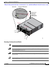
Verifying Installation of a Switching or Services Module
To verify the module installation in slot 2, follow these steps:
Step 1 Verify that the ejector levers of the module are fully closed (parallel to the faceplate) to ensure that the
module is fully seated in the backplane connectors.
Step 2 Check the captive screws of the module, the power supply, and the fan module, and tighten any loose
captive screws.
Step 3 Verify that a filler panel is installed and that the screws holding the panel in place are tightened if the
slot is to remain empty.
Step 4 Turn on the power supply switches to power up the system and check the LEDs on the module.
Note For information on how to check connectivity of the module, see the Cisco MDS 9000 Family
CLI Configuration Guide or the Cisco MDS 9000 Family Fabric Manager Configuration Guide.
FAN
STATUS
FAN-MOD-2
1
2
122003
Ejector levers flush with
module faceplate
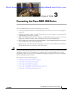
1 2 3 4 5 6 7 8 9 10 11 12 13 14 15 16
S
TA
TU
S
S
YS
TEM
R
E
SE
T
CONSOLE
MGMT 10/100
MDS 9216i
COM1
—SPEED LINK—
LINK-
—SPEEDLINK—
STATUS
1 56789
LINK— —SPEED
10 11 12 13 14234
GE1
LINK-
GE2