


Send documentation comments to mdsfeedback-doc@cisco.com
2-16
Cisco MDS 9200 Series Hardware Installation Guide
OL-17468-02
Chapter 2 Installing the Cisco MDS 9200 Series
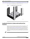
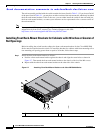
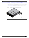
Installing the Switch in a Cabinet with Insufficient Front Clearance
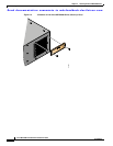
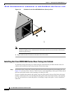
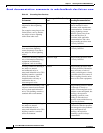
Figure 2-12 C Brackets for the Cisco MDS 9200 Series (Close-Up View)
Note Ensure the C bracket is oriented so that it blocks the fewest airflow holes on the chassis; the holes
should be slightly closer to the bottom of the brackets and the text on the back of the bracket
should be right side up.
b. Repeat with the other C bracket on the other side of the switch.
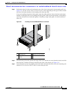
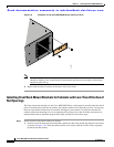
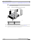
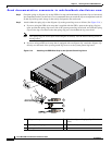
Installing the Cisco MDS 9200 Series Rear-Facing into Cabinet
To install the switch rear-facing in a cabinet using the rack-mount kit provided with the switch, for
cabinets with insufficient front-facing clearance, follow these steps:
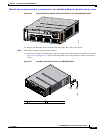
Step 1 Position the chassis in the rack, inserting the back of the chassis between the rear mounting rails (see
Figure 2-13). Use the 12-24 x 3/4-in. or 10-32 x 3/4-in. screws (depending on the type of rack) to attach
the front rack-mount brackets to the mounting rails (three per side).
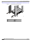
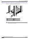
If you are installing the optional cable guides, place the cable guides in front of the front rack-mount
brackets, and then pass the screws through the cable guides, front rack-mount brackets, and mounting
rail. You can install one or both cable guides; if installing a single cable guide, it can be installed on
either side.
94297