


Send documentation comments to mdsfeedback-doc@cisco.com
2-33
Cisco MDS 9200 Series Hardware Installation Guide
OL-17468-02
Chapter 2 Installing the Cisco MDS 9200 Series
Removing and Installing Components
Warning
Blank faceplates and cover panels serve three important functions: they prevent exposure
to hazardous voltages and currents inside the chassis; they contain electromagnetic
interference (EMI) that might disrupt other equipment; and they direct the flow of cooling
air through the chassis. Do not operate the system unless all cards, faceplates, front covers,
and rear covers are in place.
Statement 1029
Installing a Switching or Services Module, Including Caching Services Modules
The following warning applies only to the Caching Services Module:
Warning
Do not touch or bridge the metal contacts on the battery. Unintentional discharge of the batteries can
cause serious burns.
Statement 341
Note Before installing any modules in the chassis, Cisco recommends installing the chassis in the rack. See
the “Installing the Chassis in a Cabinet or Rack” section on page 2-5.
To install a module in slot 2 of the chassis, follow these steps:
Step 1 Verify that there is enough clearance to accommodate any interface equipment that you connect directly
to the nearby components.
Step 2 If a filler panel is installed, remove the two Phillips pan-head screws from the filler panel and remove
the panel. To remove a currently installed module, see the “Removing and Installing Switching and
Services Modules” section on page 2-28.
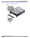
Step 3 Open fully both ejector levers on the new or replacement module (see Figure 2-18 on page 2-30).
Step 4 Position the module in the chassis as follows:
a. Position the module in the slot, aligning the sides of the module carrier with the slot guides on each
side of the slot.
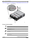
b. Slide the module carefully into the slot until the EMI gasket along the top edge of the module makes
contact with the supervisor module above it and both ejector levers have closed to approximately 45
degrees with respect to the module faceplate (see Figure 2-19 on page 2-31).
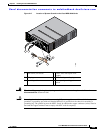
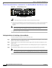
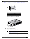
c. Grasp the two ejector levers using the thumb and forefinger of each hand and press down to create
a small 0.040-in. (1 mm) gap between the module's EMI gasket and the module above it (see
Figure 2-20).