


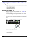
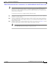
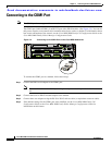
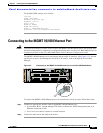
Send documentation comments to mdsfeedback-doc@cisco.com
2-38
Cisco MDS 9200 Series Hardware Installation Guide
OL-17468-02
Chapter 2 Installing the Cisco MDS 9200 Series
Removing and Installing Components
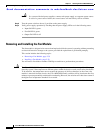
Caution In a system with dual power supplies, connect each power supply to a separate power source.
In case of a power source failure, the second source will most likely still be available.
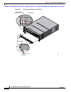
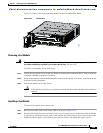
Step 8 Turn the power switch to the on (|) position on the power supply.
Step 9 Verify power supply operation by checking that the power supply LEDs are in the following states:
• Input Ok LED is green.
• Fan Ok LED is green.
• Output Fail LED is off.
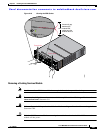
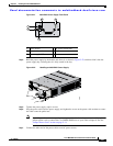
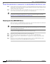
Removing and Installing the Fan Module
The fan module is designed to be removed and replaced while the system is operating without presenting
an electrical hazard or damage to the system, provided the replacement is performed promptly.
This section includes the following topics:
• Removing a Fan Module, page 2-39
• Installing a Fan Module, page 2-39
You will need a flat-blade or number 2 Phillips screwdriver to perform these procedures.
Caution The Cisco MDS 9000 Family switches have internal temperature sensors that are capable of shutting
down the system if the temperature at different points within the chassis exceed certain safety thresholds.
To be effective, the temperature sensors require the presence of airflow; therefore, in the event a fan
module is removed from the chassis, the Cisco MDS 9000 Family switches will be shut down after five
minutes to prevent potentially undetectable overheating. However, the switches will shut down sooner if
the higher-level temperature threshold is exceeded.