


Send documentation comments to mdsfeedback-doc@cisco.com
2-28
Cisco MDS 9200 Series Hardware Installation Guide
OL-17468-02
Chapter 2 Installing the Cisco MDS 9200 Series
Removing and Installing Components
Note If you purchased this product through a Cisco reseller, contact the reseller directly for technical
support. If you purchased this product directly from Cisco, contact Cisco Technical Support at
this URL: http://www.cisco.com/warp/public/687/Directory/DirTAC.shtml.
Step 10 Verify that the system software has booted and the switch has initialized without error messages. If any
problems occur, see the Cisco MDS 9000 Family Troubleshooting Guide or the Cisco MDS 9000 Family
System Messages Guide. If you cannot resolve an issue, contact your customer service representative.
Step 11 Complete the worksheets provided in Appendix D, “Site Planning and Maintenance Records” for future
reference.
Note A setup utility automatically launches the first time you access the switch and guides you through the
basic configuration. For instructions on how to configure the switch and check module connectivity, see
the Cisco MDS 9000 Family CLI Configuration Guide or the Cisco MDS 9000 Family Fabric Manager
Configuration Guide.
Removing and Installing Components
This section includes the following topics:
• Removing and Installing Switching and Services Modules, page 2-28
• Maintaining a Caching Services Module, page 2-35
• Removing and Installing Power Supplies, page 2-36
• Removing and Installing the Fan Module, page 2-38
• Removing the Cisco MDS 9200 Series, page 2-40
Warning
Hazardous voltage or energy is present on the backplane when the system is operating. Use caution
when servicing.
Statement 1034
Caution To prevent ESD damage, wear grounding wrist straps during these procedures and handle modules by
the carrier edges only.
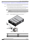
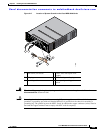
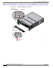
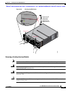
Removing and Installing Switching and Services Modules
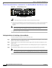
Slot 1 is reserved for the supervisor module with its integrated multiport switching or IP services
module. Slot 2 can contain an optional module. See Figure 1-2 for slot locations.
Warning
Invisible laser radiation may be emitted from disconnected fibers or connectors. Do not stare into
beams or view directly with optical instruments.
Statement 1051