


Send documentation comments to mdsfeedback-doc@cisco.com
2-23
Cisco MDS 9200 Series Hardware Installation Guide
OL-17468-02
Chapter 2 Installing the Cisco MDS 9200 Series
System Grounding
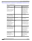
In addition, follow these guidelines when handling modules:
• Handle carriers by available handles or edges only; avoid touching the printed circuit boards or
connectors.
• Place a removed component board-side-up on an antistatic surface or in a static shielding container.
If you plan to return the component to the factory, immediately place it in a static shielding
container.
• Never attempt to remove the printed circuit board from the metal carrier.
Caution For safety, periodically check the resistance value of the antistatic strap. The measurement should be
between 1 and 10 megohm (Mohm).
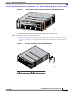
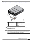
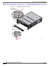
Establishing the System Ground
This section describes how to connect a system ground to the MDS 9200 series switches.
Note This system ground is also referred to as the network equipment building system (NEBS) ground.
You must use the system (NEBS) ground on AC-powered systems if you are installing this equipment in
a U.S. or European Central Office.
The system (NEBS) ground provides additional grounding for EMI shielding requirements and
grounding for the low voltage supplies (DC-DC converters) on the modules and is intended to satisfy the
telcordia Technologies NEBS requirements for supplemental bonding and grounding connections. You
must observe the following system grounding guidelines for your chassis:
• You must install the system (NEBS) ground connection with any other rack or system power ground
connections that you make. The system ground connection is required if this equipment is installed
in a U.S. or European Central Office.
• You must connect both the system (NEBS) ground connection and the power supply ground
connection to an earth ground. The system (NEBS) ground connection is required if this equipment
is installed in a U.S. or European Central Office.
• You do not need to power down the chassis because the MDS 9200 series chassis are equipped with
AC-input power supplies.
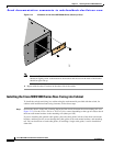
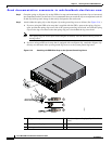
Required Tools and Equipment
To connect the ground system, you need the following tools and materials:
• Grounding lug—A two holes standard barrel lug. Supports up to 6 AWG wire. Supplied as part of
accessory kit.
• Grounding screws—Two M4 x 8mm (metric) pan-head screws. Supplied as part of the accessory kit.
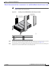
• Grounding wire—Not supplied as part of accessory kit. The grounding wire should be sized
according to local and national installation requirements. Depending on the power supply and
system, a 12 AWG to 6 AWG copper conductor is required for U.S. installations. Commercially
available 6 AWG wire is recommended. The length of the grounding wire depends on the proximity
of the switch to proper grounding facilities.
• No. 1 Phillips screwdriver.