


Send documentation comments to mdsfeedback-doc@cisco.com
2-11
Cisco MDS 9200 Series Hardware Installation Guide
OL-17468-02
Chapter 2 Installing the Cisco MDS 9200 Series
Installing the Switch in a Cabinet with Insufficient Front Clearance
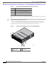
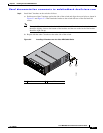
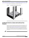
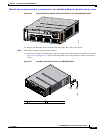
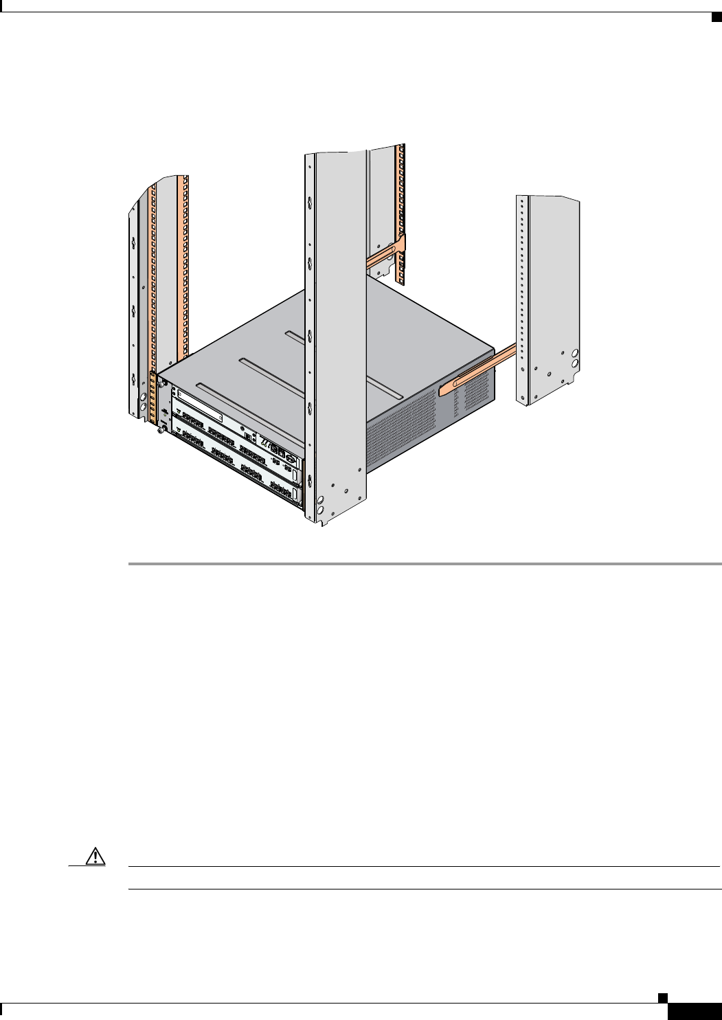
Figure 2-6 shows the Cisco MDS 9200 Series completely installed in a rack.
Figure 2-6 Cisco MDS 9200 Series Chassis Installed in the Rack
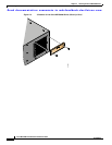
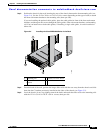
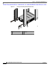
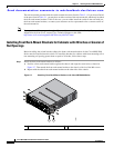
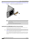
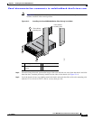
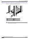
Installing the Switch in a Cabinet with Insufficient Front
Clearance
This section describes how to use the rack-mount kit provided with the switch to install the Cisco MDS
9200 Series into a cabinet with insufficient front-facing clearance. The Cisco MDS 9200 Series is
installed rear-facing to provide adequate clearance for the fiber-optic cables. This cabinet meets the
requirements described in Appendix A, “Cabinet and Rack Installation,” except the cabinet has less than
three inches of clearance between the inside of the front door or bezel panel and the front cabinet
mounting rails. This rear-facing installation is necessary to ensure that the minimum bend radius for the
fiber-optic cables is maintained. In these cabinets, the Cisco MDS 9200 Series is mounted backwards,
with the fiber-optic cables facing toward the rear of the cabinet and the power supplies facing the front
of the cabinet.
Caution If the rack is on wheels, ensure that the brakes are engaged or that the rack is otherwise stabilized.
MDS 9216i
G
E
1
L
I
N
K
G
E
2
L
IN
K
5
6
7
8
9
1
0
1
1
1
2
1
3
1
4
1
2
3
4
116894