


Send documentation comments to mdsfeedback-doc@cisco.com
2-14
Cisco MDS 9200 Series Hardware Installation Guide
OL-17468-02
Chapter 2 Installing the Cisco MDS 9200 Series
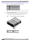
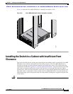
Installing the Switch in a Cabinet with Insufficient Front Clearance
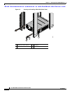
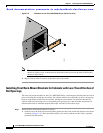
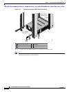
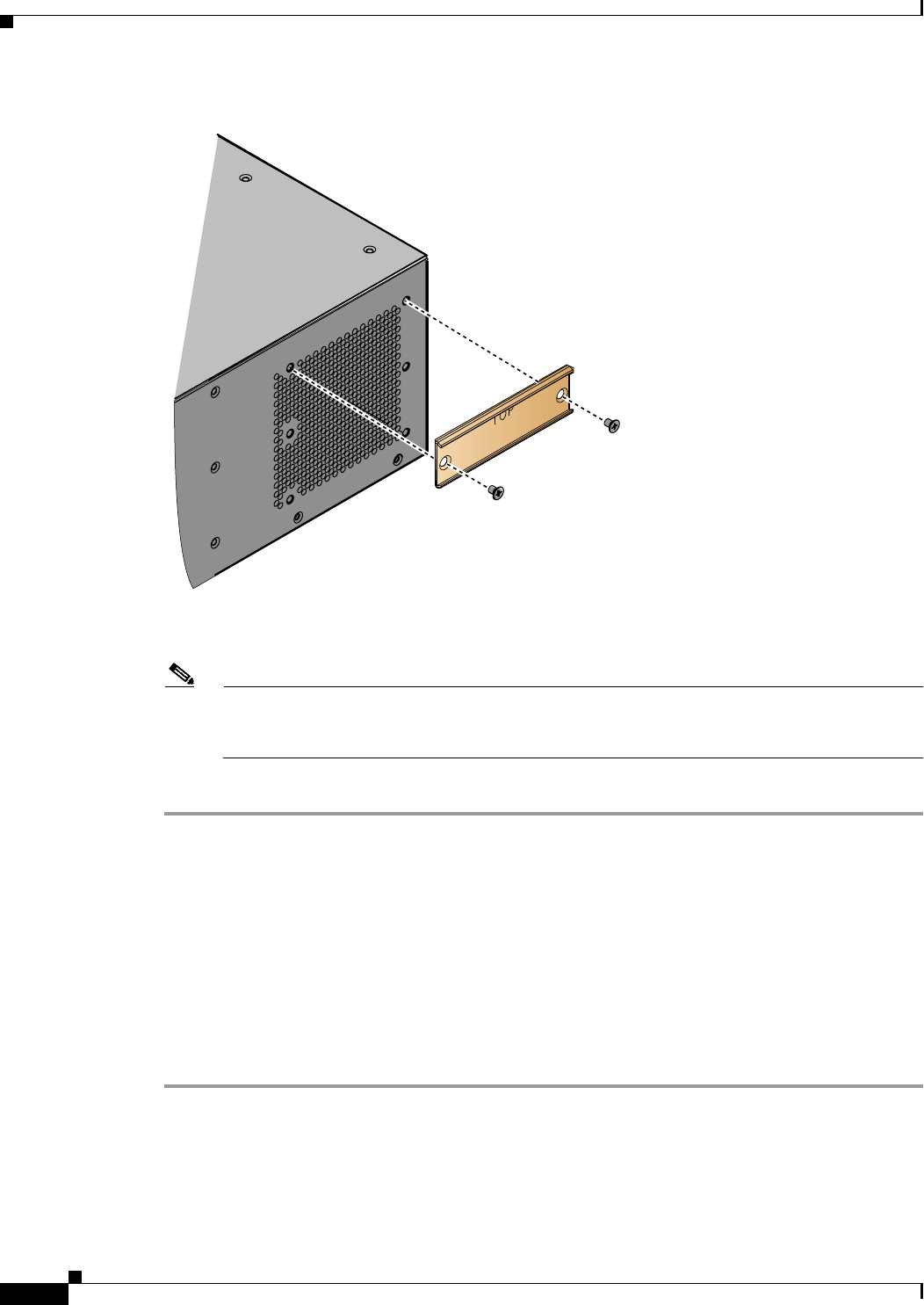
Figure 2-9 C Brackets for the Cisco MDS 9200 Series (Close-Up View)
Note Ensure the C bracket is oriented so that it blocks the fewest airflow holes on the chassis; the holes
should be slightly closer to the bottom of the brackets and the text on the back of the bracket
should be right side up.
b. Repeat with the other C bracket on the other side of the switch.
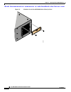
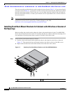
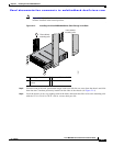
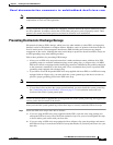
Installing Front Rack-Mount Brackets for Cabinets with Less Than 26 Inches of
Rail Spacings
The front rack-mount brackets for the Cisco MDS 9200 Series switch must be installed onto the switch
prior to installing the switch into the cabinet. For cabinets with less than 26 inches of rail-to-rail spacing,
the front rack-mount bracket must be installed 180 degrees from normal. To install the brackets for
cabinets with front-mounting rail to rear-mounting rail spacing of less than 26 inches that need to be
mounted backwards to maintain adequate fiber-optic clearance, follow these steps:
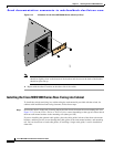
Step 1 Install the front rack-mount brackets as follows:
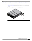
a. Position one of the front rack-mount brackets against the side of the switch and align the screw holes
as shown in Figure 2-10. Then attach the bracket to the switch with the six M4 screws originally
provided with the bracket.
94297