


Send documentation comments to mdsfeedback-doc@cisco.com
C-5
Cisco MDS 9200 Series Hardware Installation Guide
OL-17468-02
Appendix C Cable and Port Specifications
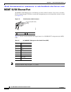
MGMT 10/100/1000 Ethernet Port
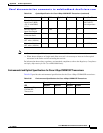
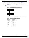
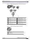
Table C-6 lists the connector pinouts and signal names for a 10/100/1000BASE-T management port
(MDI) cable.
Note The RJ-45 interface only uses pins 1, 2, 3, and 6.
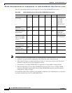
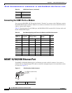
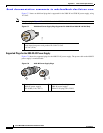
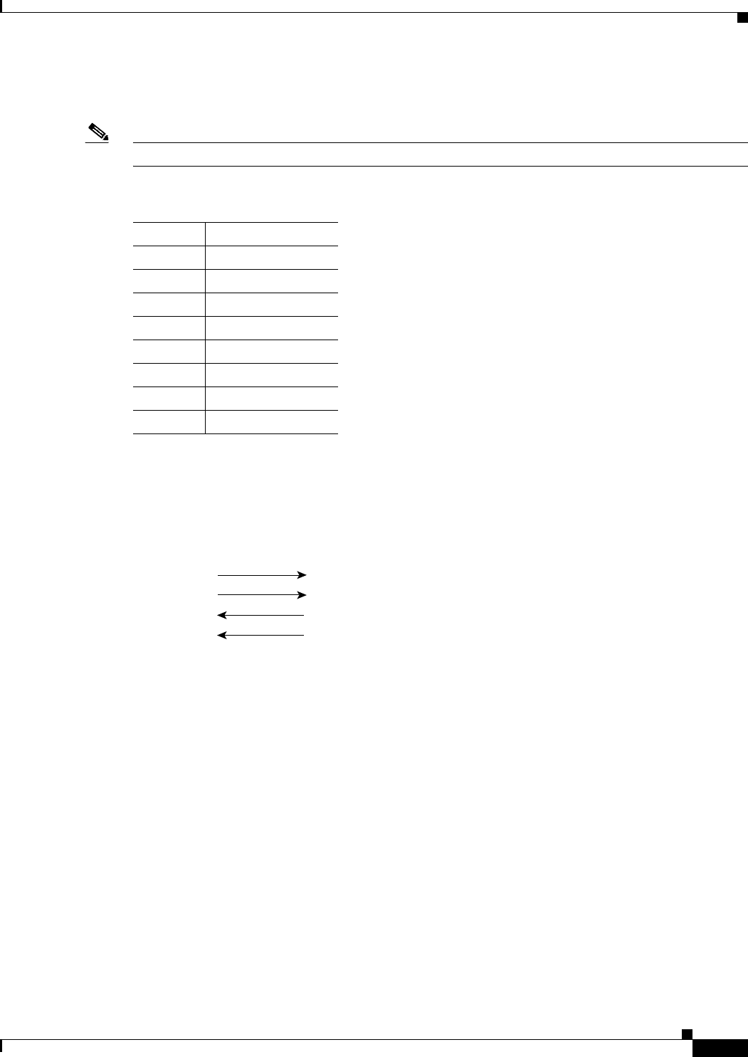
Figure C-2 shows a schematic of the 10/100/1000BASE-T cable required to connect the management
port to a switch or hub (not provided with the switch).
Figure C-2 Twisted-Pair 10/100/1000BASE-T Cable Schematic
Table C-6 10/100/1000BASE-T Management Port Cable Pinout (MDI)
Pin Signal
1TD+
2TD-
3RD+
6RD–
4Not used
5Not used
7Not used
8Not used
1 TXD+
2 TXD-
3 RXD+
6 RXD-
1 RXD+
MGMT 10/100
Switch/Hub
2 RXD-
3 TXD+
6 TXD-
4NC
5NC
7NC
8NC
4NC
5NC
7NC
8NC
99343