


Send documentation comments to mdsfeedback-doc@cisco.com
2-27
Cisco MDS 9200 Series Hardware Installation Guide
OL-17468-02
Chapter 2 Installing the Cisco MDS 9200 Series
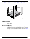
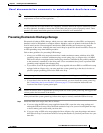
Starting Up the Switch
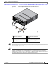
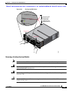
Step 2 Verify that both power supplies and the fan module are installed.
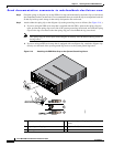
Step 3 Verify that the power switches on both power supplies are off, and then plug the power cables into the
power supplies and tighten the screws on the power cable retainers to ensure the cables cannot be pulled
out.
Note Depending on the outlet receptacle on your power distribution unit, you may need the optional
jumper power cord to connect the Cisco MDS 9200 Series to your outlet receptacle. See the
“Jumper Power Cord” section on page C-11.
Step 4 Connect the other end of the power cables to an AC power source.
Step 5 Ensure that the switch is adequately grounded as described in the “Installing the Switch in a Cabinet with
Insufficient Front Clearance” section on page 2-11, and that the power cables are connected to outlets
that have the required AC power voltages (see the “Weight of Modules” section on page B-3).
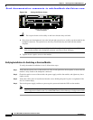
Step 6 Flip the power switches on the power supplies to the on (|) position. The switch boots automatically.
Step 7 Listen for the fans; they should begin operating when the switch is powered on.
Caution Do not operate the switch without a functioning fan module except for during the brief fan
module replacement procedure. Cisco MDS 9000 Family switches can operate for only a few
minutes without any functioning fan modules before they begin to overheat.
Step 8 After the switch boots, verify that the LED behavior is as follows:
• Fan module: Status LED is green.
• Power supplies:
–
Input Ok LED is green.
–
Fan Ok LED is green.
–
Output Fail LED is off.
• Supervisor, switching, or services modules:
–
During initialization, the status LED on the module flashes orange once, remains orange during
diagnostic boot tests, then turns green when the module is operational (online). If the system
software is unable to start up, this LED remains orange or turns red.
–
After initialization, the status LED is green, indicating that all chassis environmental monitors
are reporting that the system is operational. If this LED is orange or red, then one or more
environmental monitor is reporting a problem.
• The Link LEDs for the Ethernet port should not be on unless the cable is connected.
Note The link LEDs for the Fibre Channel ports remain yellow until the ports are enabled, and the
LED for the MGMT 10/100 Ethernet port remains off until the port is connected.
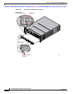
Step 9 Try removing and reinstalling a component that is not operating correctly. If it still does not operate
correctly, contact your customer service representative for a replacement.