


Send documentation comments to mdsfeedback-doc@cisco.com
1-10
Cisco MDS 9200 Series Hardware Installation Guide
OL-17468-02
Chapter 1 Product Overview
Interface Modules
Interface Modules
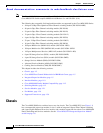
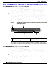
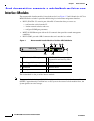
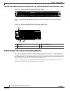
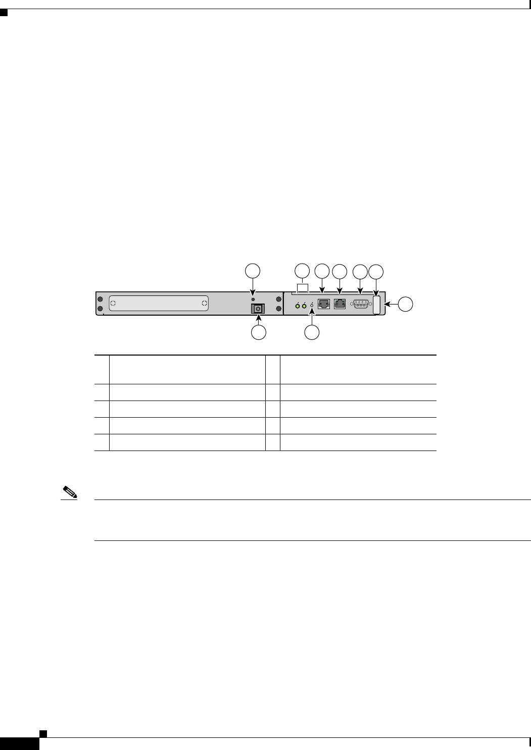
The nonremovable interface module is located above slot 1 (see Figure 1-7) and is identical for all Cisco
MDS 9200 Series switches. It provides the following local and remote management interfaces:
• RS-232 (EIA/TIA-232) console port with an RJ-45 connection that you can use to:
–
Configure the switch from the CLI.
–
Monitor network statistics and errors.
–
Configure SNMP agent parameters.
• MGMT 10/100 Ethernet port with an RJ-45 connection that provides network management
capabilities.
• RS-232 COM1 port with a DB-9 connector that can be attached to a modem.
Figure 1-7 Nonremoveable Interface Module of the Cisco MDS 9200 Series
The clock module is also part of the interface module.
Note The system clocks in the Cisco MDS 9200 Series have a field-measured mean time between failures
(MTBF) of approximately 3.2 million hours or 365 years. In the event of a clock module failure, the
system generates an error message.
1 ESD socket (for ESD strap) 6 MGMT 10/100 Ethernet port (with
integrated Link and Activity LEDs)
2 Grounding pad (beneath tape) 7 COM1 port
3 Status and System LEDs 8 Asset tag
4 Reset button 9 Interface module
5 Console port
S
T
A
T
U
S
S
Y
S
T
E
M
R
E
S
E
T
CONSOLE
MGMT 10/100
MDS 9216i
9
3
1
5
6
42
116890
COM1
7
8