


Installing System Components 103
6
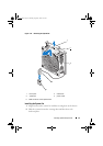
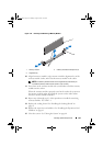
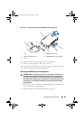
Press down and out on the ejectors on each end of the socket until the
memory module pops out of the socket. See Figure 3-14.
Handle each memory module only on either card edge, making sure not to
touch the middle of the memory module.
NOTE: If you are not replacing the memory module, insert a memory module
blank in the socket.
7
Replace the cooling shroud. See "Installing the Cooling Shroud" on
page 83.
8
Replace the expansion card stabilizer. "Installing the Expansion Card
Stabilizer" on page 81.
9
Close the system. See "Closing the System" on page 80.
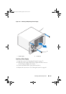
10
Place the system upright on a flat surface.
11
Reattach any peripherals and connect the system to an electrical outlet.
12
Turn on the system and attached peripherals.
Expansion Cards
Expansion Card Installation Guidelines
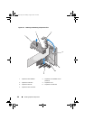
Your system supports five PCIe Generation 2 expansion cards. To identify the
expansion slots see Figure 6-1.
• The expansion slots support one full-length, and four half-length cards.
• The expansion-card slot is not hot-swappable.
CAUTION: To ensure proper cooling, only one of the two expansion cards
can have a power consumption of greater than 15 W (up to 25 W maximum),
not including the integrated storage controller.
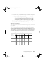
• Table 3-2 provides a guide for installing expansion cards to ensure proper
cooling and mechanical fit. The expansion cards with the highest priority
should be installed first using the slot priority indicated. All other
expansion cards should be installed in card priority and slot priority order.
book.book Page 103 Monday, August 9, 2010 3:07 PM