


VFD-F Series
DELTA ELECTRONICS, INC. ALL RIGHTS RESERVED
5-68
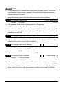
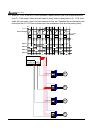
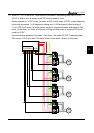
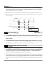
If multi-function input terminals (04-00 to 04-07) are set to 27 to 31, the corresponding
output terminals will skip and not activate. The following diagram is the action schedule of
time circulation when motor 3 is disabled.
The motor, which is running with AC drive doesn’t accept any disable command of motor.
When switching time circulation, AC drive won’t provide this selection when running motor
is coast to stop.
Output
Frequency
03-00 01
=
Run
Motor 3 disable
03-01 02
=
03-02 03
=
03-03 04
=
11-04
11-03
11-01 01
11-02 04
04-00 29
=
=
=
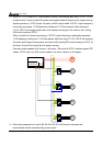
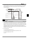
11 - 04 Motor Switch Delay Time
Factory Setting: 1.0
Settings 0.0~3600.0 sec Unit: 0.1
This parameter determines time interval of two motors during circulative control (11-01=01).
Users need to set suitable time delay to avoid water hammer effect damaging AC drive,
motor or system.
This parameter determines time interval between power supply changes from AC drive to
commercial power during fixed circulative control (11-01=02). Users need to set the suitable
time delay to make no shock to motor and runs by commercial power.
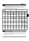
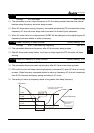
11 - 05
Motor Switch Delay Time during Fixed Amount
Circulation
Factory Setting: 10.0
Settings 0.0~3600.0 sec Unit: 0.1
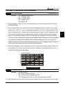
This parameter determines time interval between motor switch frequency and power supply
of motor is not from AC drive during fixed amount circulation (11-01=02)/fixed amount
control (11-01=03) and output frequency of AC drive attained.
As the diagram shown below, after output frequency attains 11-06 motor switch frequency,
motor doesn’t switch at once. It will do motor switch action of circulation control after waiting
the delay time that is set by 11-05. Suitable delay time setting will decrease motor switch
times.