


5
VFD-F Series
DELTA ELECTRONICS, INC. ALL RIGHTS RESERVED
5-15
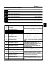
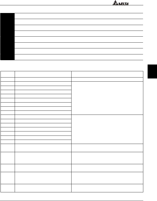
5.4 Group 3: Output Function Parameters
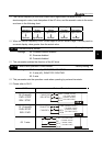
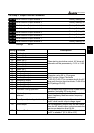
03 - 00 Multi-function Output terminal 1
Factory Setting: 00
03 - 01 Multi-function Output terminal 2
Factory Setting: 00
03 - 02 Multi-function Output terminal 3
Factory Setting: 00
03 - 03 Multi-function Output terminal 4
Factory Setting: 00
03 - 04 Multi-function Output terminal 5
Factory Setting: 00
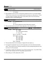
03 - 05 Multi-function Output terminal 6
Factory Setting: 00
03 - 06 Multi-function Output terminal 7
Factory Setting: 00
03 - 07 Multi-function Output terminal 8
Factory Setting: 00
Settings 00-33
Setting Functions Descriptions
00 No function
01 Motor No. 1
02 Motor No. 2
03 Motor No. 3
04 Motor No. 4
05 Motor No. 5
06 Motor No. 6
07 Motor No. 7
08 Motor No. 8
When starting circulative control, AC drive will
automatic set this parameter by 11-01 to 11-03.
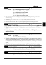
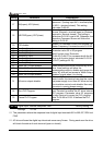
09 Auxiliary 1 output
10 Auxiliary 2 output
11 Auxiliary 3 output
12 Auxiliary 4 output
13 Auxiliary 5 output
14 Auxiliary 6 output
15 Auxiliary 7 output
Parameter value 09 to 15 program
Multi-Function Output Terminals
(Pr.03-00~Pr.03-07) to correspond with the AC
drive multi-function input terminals, Pr.04-00 to
04-07(settings 20~26).
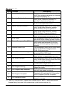
16 Indication during operation The corresponding output will be closed during
operation (including DC brake time).
17 Master frequency
attained
The corresponding output will be closed when
output frequency reaches master frequency
command.
18 Zero Speed (including shutdown) The corresponding output will be closed when
the AC drive has no output voltage signal.
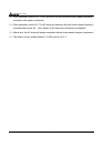
19 Over-torque The corresponding output relay will be closed
when the AC drives output current exceeds the
over-torque detection level 06-04.
20 External Fault The corresponding output will be closed when
the EF is enabled. (Pr. 4-00 to 4-07)