


5
VFD-F Series
DELTA ELECTRONICS, INC. ALL RIGHTS RESERVED
5-39
5.9 Group 8: Special Parameters
08 - 00 DC Brake Current Level
Factory Setting: 00
Settings 00~100% Unit: 1
This parameter determines the level of DC brake current output.
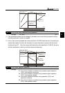
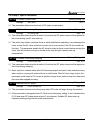
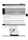
08 - 01 DC Brake Time during Start-up
Factory Setting: 0.0
Settings 0.0~60.0 Sec Unit: 0.1
This parameter determines the duration of time that the DC brake current will be applied to
the motor during the AC drive start-up.
The motor may rotate by external force or inertia itself before operating. It may damage the
motor or start the AC drive protection function by an over current if the AC drive added at
this time. This parameter enable the AC drive to output a direct current before running the
motor that will produce a torque to forced motor stop and get a steady start-up
characteristic.
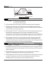
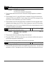
08 - 02 DC Brake Time during Stopping
Factory Setting: 0.0
Settings 0.00~60.00 Sec Unit: 0.01
This parameter determines the duration of time that the DC brake current will be applied to
the motor during stopping.
Motor may be in rotation status after AC drive stops output and can’t in stop status accuracy
when motor is running with external force or itself inertia. After AC drive stops output, this
parameter could output a DC current to produce torque force motor to stop and make sure
the motor has stopped accuracy.
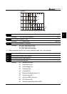
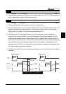
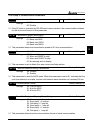
08 - 03 Start-point for DC Brake
Factory Setting: 0.00
Settings 0.00~120.00 Hz Unit: 0.01
This parameter determines the frequency when DC brake will begin during deceleration.
If this parameter is set greater than 01-05 minimum frequency setting, it won’t decelerate to
01-05 and enter DC brake status when AC drive brakes. Suitable DC brake start-up
frequency setting will get better brake characteristic.