


VFD-F Series
DELTA ELECTRONICS, INC. ALL RIGHTS RESERVED
5-62
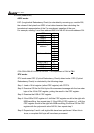
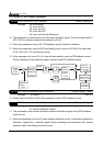
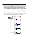
Output frequency of PID controller will filter by primary low pass function. This function
could decrease change of output frequency. A long primary low pass time means filter
degree is high and vice versa.
Unsuitable primary low pass filter time setting may cause system oscillation.
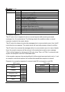
10 - 08 PID Feedback Signal Range
Factory Setting: 600.0
Settings 0.0~6550.0 Unit:0.1
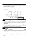
This parameter setting could allow the maximum of PID deviation.
If PID function is normal, it should control the detective value to target value accurately in
the certain time. If AC drive can’t control deviation in the 10-08 setting range during 10-09
setting time, FbL warning will pup-up and it means PID feedback control is abnormal. The
treatment is set as 10-10.
10 - 09 PID Feedback Signal Fault Treatment Time
Factory Setting: 0.0
Settings 0.0~3600.0 Sec Unit: 0.1
This parameter is to set the detection time of abnormal PID derivative. If PID deviation
detection time is set to 0.0, the function is disabled.
10 - 10 PID Feedback Signal Fault Treatment
a
Factory Setting: 01
Settings 00: Warn and RAMP stop
01: Warn and COAST stop
02: Warn and keep operating
This parameter is to set treatment of the abnormal PID deviation.
10 - 11 PID Minimum Output Frequency
a
Factory Setting: 01
Settings 0: By PID controller
1: By AC drive
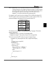
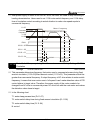
This parameter can decide the source of PID output minimum frequency when AC drive
enters PID sleep process. If it is set to 0, minimum output frequency should be set by PID. If
it is set to 1 and 01-08 is 0, the output frequency is equal to the value of 01-05 setting. If it is
set to 1 and 01-08 is not 0, the output frequency is equal to the value of 01-08 setting.