


VFD-F Series
DELTA ELECTRONICS, INC. ALL RIGHTS RESERVED
3-2
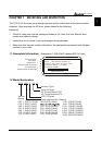
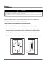
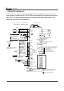
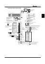
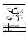
3.1 Basic Wiring Diagram
Users must connect wires according to the following circuit diagram shown below. Do not
plug a Modem or telephone line to the RS-485 communication port, permanent damage may
result. Pins 1 & 2 are the power sources for the optional copy keypad and should not be
used while using RS-485 communication.
*RS-485
R(L1)
S(L2)
T(L3)
NFB
R
S
T
RB
RC
+1 +2/B1
B2
SA
OFF
ON
MC
MC
E
1:+EV
2:GND
3:SG-
4:SG+
5:NC
6:NC
-
MI1
MI2
MI3
MI4
MI5
MI6
MI8
MI7
DCM
EF
AVI
ACI1
ACI2
ACM
Master Frequency
)
0~10V (47k
4~20mA
+10V
5k
3
2
1
Sw1
Sink
Source
E
NOTE
U(T1)
V(T2)
W(T3)
M
3~
RA1
RB1
RC1
E
A
FM1
ACM
Factory setting: output frequency
0~10Vdc/2mA
E
RA2
RB2
RC2
A
FM2
Factory setting: output current
0~20mA/4~20mA
500
Ω
Max. Impedance:
RA3
RC3
RA4
RC4
RA5
RC5
RA6
RC6
RA7
RC7
RA8
RC8
Relay B.D.
RY00
4~20mA
0-10V
0-5V
SW2
FWD
REV
24V
Power Supply
+10V 20mA
For 230V series, 1~15HP models
460V series, 1~20HP models
Brake Resistor
(Optional)
Motor
NFB
FWD/STOP
REV/STOP
E.F.
Multi-step 1
Multi-step 2
Multi-step 3
Multi-step 4
RESET
JOG
Accel/Decel Prohibit
1/2 Accel/Decel Switch
Digital Signal Common
Factory
Setting
Factory Setting:
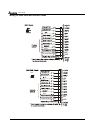
Sink Mode
Don't apply the mains voltage
directly to above terminals.
Multi-
function
Input
Terminals
Analog Signal Common
Serial Communication
Interface
Main circuit (power) terminals
Control circuit terminals
Shielded leads&cable
Optional
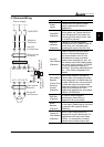
Please refer to the following
wiring for Sink mode and
Source mode.
240VAC 2.5A
120VAC 5A
28VDC 5A
Multi-function indication
output contacts
Factory setting: no function
Factory setting:
no function
Multi-function analog output terminals
Analog Signal Common
Recommended circuit
when power supply is
turned OFF by a fault
output.
If the fault occurs, the
contact will be ON to turn
off the power and protect the power system.