


VFD-F Series
DELTA ELECTRONICS, INC. ALL RIGHTS RESERVED
5-58
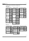
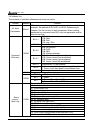
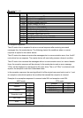
Content Address Function
2102H Frequency command (F)
2103H Output frequency (H)
2104H Output current (AXXX.X)
2105H DC-BUS Voltage (UXXX.X)
2106H Output voltage (EXXX.X)
2107H Output power factor (n)
2108H Output power (XX. XXKW)
2109H Feedback signal actual value
210AH Feedback signal (XXX.XX %)
210BH Estimated torque ratio (XXX.X)
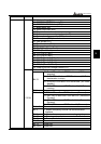
210CH User Target Value (Low bit) uL 0-99.99
210DH User Target Value (High bit) uH 0-9999
210EH PLC time
220FH Reserved
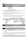
3.6 Exception response
The AC motor drive is expected to return a normal response after receiving command
messages from the master device. The following depicts the conditions when no normal
response is replied to the master device.
The AC motor drive does not receive the messages due to a communication error; thus, the AC
motor drive has no response. The master device will eventually process a timeout condition.
The AC motor drive receives the messages without a communication error, but cannot handle
them. An exception response will be returned to the master device and an error message
“CExx” will be displayed on the keypad of AC motor drive. The xx of “CExx” is a decimal code
equal to the exception code that is described below.
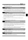
In the exception response, the most significant bit of the original command code is set to 1, and
an exception code which explains the condition that caused the exception is returned.
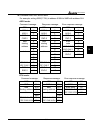
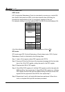
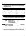
Example of an exception response of command code 06H and exception code 02H:
ASCII mode RTU mode
STX ‘:’ Address 01H
‘0’ Function 86H
Address
‘1’ Exception code 02H
‘8’ CRC CHK Low C3H
Function
‘6’ CRC CHK High A1H
‘0’
Exception code
‘2’
‘7’
LRC CHK
‘7’
CR
END
LF