


8
VFD-F Series
DELTA ELECTRONICS, INC. ALL RIGHTS RESERVED
8-5
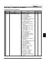
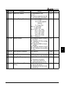
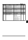
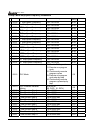
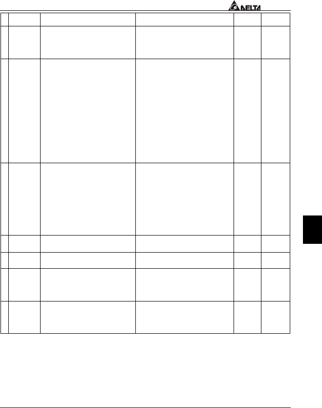
Parameters Functions Settings
Factory
Setting
Customer
02-07 Loss of ACI Signal 00: Decelerate to 0Hz
01: E.F.
02: Continue operation by the
last frequency command
01
a
02-08 Start-up Display Selection Bit0~1: 00 = F LED
01 = H LED
10 = U LED (special
display)
11 = Fwd / Rev
Bit2: 0 = Fwd LED /
1 = Rev LED
Bit3~5: 000 = 1st 7-step
001 = 2nd 7-step
010 = 3rd 7-step
011 = 4th 7-step
100 = 5th 7-step
Bit6~7: Reserved
00
a
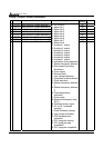
02-09 Special Display 00: A displays output current of
AC drive
01: U displays DC-Bus voltage
of AC drive
02: E displays RMS of output
voltage
03: P displays feedback Signal
04: PLC display auto procedure
state
00
a
02-10 User Defined Coefficient 0.01~160.00
1.00
a
02-11 Flying Start 00: Disable
01: Enable (Dc brake disabled)
00
a
02-12 Flying Start Frequency 00: Trace from master
frequency command
01: Trace from maximum
setting frequency 01-00
00
a
02-13 Master Frequency Memory
Setting
00: Do not remember the last
known frequency
01: Remember the last known
frequency
01