


VFD-F Series
DELTA ELECTRONICS, INC. ALL RIGHTS RESERVED
5-60
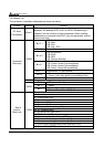
5.11 Group 10: PID Control Parameters
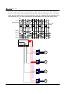
10 - 00 Input Terminal for PID Feedback
Factory Setting: 00
Settings
00: No function
01: Input via AVI
02: Input via ACI1
03: Input via ACI2
04: Input via External Reference
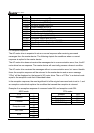
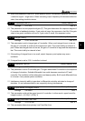
This parameter is to set the source of PID control feedback signal. The source could be AVI,
ACI1, ACI2 or external reference that defined by 04-24.
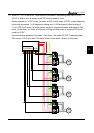
When this parameter is set to 00, PID feedback control function is disabled.
When this parameter is set to 02/03 and analog input current of ACI1/ACI2 is lower than
Pr.04-13/Pr.04-17, EF warning will pup-up.
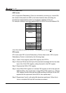
If this parameter isn’t set to 00, AC drive will automatically start-up PID feedback control.
Output frequency is calculated by master frequency and PID feedback signal.
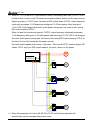
P
10-03
I
10-04
10-01
+
+
+
+
Target
value
02-00
Detection
Signal
10-02
Position/
Negative
Feedback
Difference
Range
D
10-05
10-06
Upper
Bound for
Integral
Control
10-07
Primary
Low Pass
FilterTime
01-07/01-08
Upper/Lower
bound Freq.
Frequency
Command
10 - 01 PID Control Detection Signal Reference
Factory Setting: 1000.0
Settings 0.0-6550.0 Unit: 0.1
Please refer to 04-09 to 04-20 if this parameter is set to PID feedback control.
10 - 02 PID Feedback Control Method
Factory Setting: 00
Settings
00: Negative feedback control
01: Positive feedback control
This parameter could set the calculation method of deviation signal during PID feedback
control circuit.
When this parameter is set to 00: when negative feedback control, the deviation equation is
deviation = target value – detection signal. When increasing output frequency will increase
detection value, this setting should be chose.