


A
VFD-F Series
DELTA ELECTRONICS, INC. ALL RIGHTS RESERVED
A-1
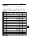
Specifications
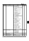
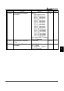
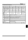
Voltage Class 230V Class
Model Number VFD-_ _ _F23_
007 015 022 037 055 075 110 150 185 220 300 370
Max. Applicable Motor Output (kW)
0.75 1.5 2.2 3.7 5.5 7.5 11 15 18.5 22 30 37
Max. Applicable Motor Output (HP)
1.0 2.0 3.0 5.0 7.5 10 15 20 25 30 40 50
Rated Output Capacity (KVA)
1.9
2.5 4.2 6.5 9.5 12.5 18.3 24.7 28.6 34.3 45.7 55
Rated Output Current (A)
5.0
7.0 11 17 25 33 49 65 75 90 120 145
Maximum Output Voltage (V) Proportional to Input Voltage
Rated Frequency (Hz) 0.10-120.00Hz
Output Rating
Carrier Frequency (kHz)
4-10 3-9 2-6
Rated Input Current (A)
5.7 7.6 15.5 20.6 26 34 50 60 75 90 110 142
Rated Voltage 3-phase 180-264 V
Input
Ratin
g
Frequency Tolerance 47 – 63 Hz
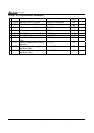
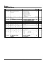
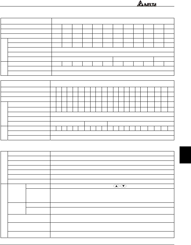
Voltage Class 460V Class
Model Number VFD-_ _ _F43_
007 015 022 037 055 075 110 150 185 220 300 370 450 550 750 900 1100 1320 1600 1850 2200
Max. Applicable Motor Output (kW)
0.75 1.5 2.2 3.7 5.5 7.5 11 15 18.5 22 30 37 45 55 75 90 110 132 160 185 220
Max. Applicable Motor Output (HP)
1.0 2.0 3.0 5.0 7.5 10 15 20 25 30 40 50 60 75 100 125 150 175 215 250 300
Rated Output Capacity (KVA)
2.3 3.2 4.2 6.5 10 14 18 25 29 34 46 56 69 84 114 137 168 198 236 281 350
Rated Output Current (A)
2.7 4.2 5.5 8.5 13 18 24 32 38 45 60 73 91 110 150 180 220 260 310 370 460
Maximum Output Voltage (V) Proportional to Input Voltage
Rated Frequency (Hz) 0.10-120.00Hz
Output Rating
Carrier Frequency (kHz)
4-10 3-9 2-6
Rated Input Current (A)
3.2 4.3 5.9 11.2 14 19 25 32 39 49 60 73 91 120 160 160 200 240 300 380 400
Rated Voltage 3-phase 342-528 V
Input
Ratin
g
Frequency Tolerance 47 – 63 Hz
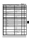
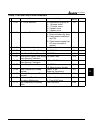
General Specifications
Control System SPWM (Sinusoidal Pulse Width Modulation, carrier frequency 2-10kHz)
Output Frequency Resolution 0.01Hz
Torque Characteristics Including the auto-torque, auto-slip compensation; starting torque can be 150% at 1.0Hz
Overload Endurance 120% of rated current for 1 minute
Accel/Decel Time 1-36000/0.1-3600.0/0.01-360.00 seconds (3 Independent settings for Accel/Decel Time)
V/f Pattern Adjustable V/f pattern
Control Characteristics
Stall Prevention Level 20 to 150%, Setting of Rated Current
Keypad
Setting by
Frequency
Setting
External Signal
1 set of AVI analog voltage DC0-+10V/0-+5V, 2 sets of ACI analog current 0/4-20mA,
15 Multi-Function Inputs, RS-485 interface (MODBUS), External terminals UP/DOWN
Key
Keypad Set by RUN, STOP and JOG Operation
Setting
Signal
External Signal
Operation by FWD, REV, JOG and communication operation
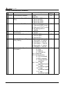
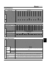
Multi-Function Input Signal
Multi-step selection 0 to 15, Jog, accel/decel inhibit, first to forth accel/decel switches,
counter, external Base Block (NC, NO), JOG, auxiliary motor start/maintenance
Multi-Function Output
Indication
AC Drive Operating, Frequency Attained, Desired Frequency Attained, Zero speed, Base
Block, Fault Indication, Local/Remote indication, and Auxiliary Motor Output
Operating Characteristics
Analog Output Signal 2 sets of Analog frequency/current signal output