


VFD-F Series
DELTA ELECTRONICS, INC. ALL RIGHTS RESERVED
8-4
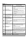
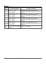
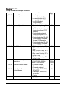
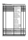
Group 2 Digital Output/Input Parameter
Parameters Functions Settings
Factory
Setting
Customer
a
02-00 Source of Frequency
Command
00: via keypad
01: via analog input AVI
02: via analog input ACI1
03: via analog input ACI2
04: via RS485 serial
communication
05: via External Reference
00
a
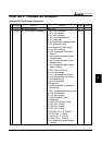
02-01 Source of Operation
Command
00: Controlled by the digital
keypad
01: Controlled by the external
terminals, keypad STOP
enabled.
02: Controlled by external
terminals, keypad STOP
disabled.
03: Controlled by the RS-485
communication interface,
keypad STOP enabled.
04: Controlled by the RS-485
communication interface,
keypad STOP disabled.
00
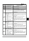
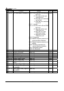
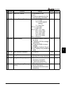
02-02 Stop Method 00:Stop = ramp to stop, E.F.
(External Fault) = coast to
stop
01:Stop = coast to stop, E.F. =
coast to stop
02:Stop = ramp to stop, E.F. =
ramp to stop
03:Stop = coast to stop, E.F. =
ramp to stop
00
a
02-03 PWM Carrier Frequency
Selections
1~10HP: 4000~10000Hz
15~30HP: 3000~9000Hz
≧40HP: 2000~6000Hz
9000Hz
6000Hz
4000Hz
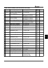
02-04 Forward/Reverse Enable 00: Forward enabled
01: Reverse disabled
02: Forward disabled
00
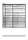
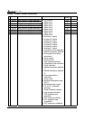
02-05 2-wire/3-wire Operation
Control Modes
00: 2-wire (#1), FWD/STOP,
REV/STOP
01: 2-wire (#2), RUN/STOP,
REV/FWD
02: 3-wire
00
02-06 Line Start Lockout 00: Disabled
01: Enabled
01