


5
VFD-F Series
DELTA ELECTRONICS, INC. ALL RIGHTS RESERVED
5-49
3. Communication Protocol
3.1 Communication Data Frame:
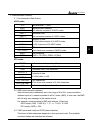
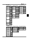
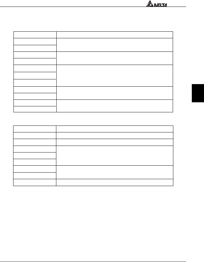
ASCII mode:
STX Start character ‘:’ (3AH)
ADR 1
ADR 0
Communication address:
8-bit address consists of 2 ASCII codes
CMD 1
CMD 0
Command code:
8-bit command consists of 2 ASCII codes
DATA (n-1)
…….
DATA 0
Contents of data:
N X 8-bit data consists of 2n ASCII codes.
n<=25, maximum of 50 ASCII codes
LRC CHK 1
LRC CHK 0
LRC check sum:
8-bit check sum consists of 2 ASCII codes
END 1
END 0
End characters:
END1= CR (0DH), END0= LF(0AH)
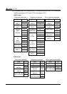
RTU mode:
START A silent interval of more than 10 ms
ADR Communication address: 8-bit address
CMD Command code: 8-bit command
DATA (n-1)
…….
DATA 0
Contents of data:
N X 8-bit data, n<=25
CRC CHK Low
CRC CHK High
CRC check sum:
16-bit check sum consists of 2 8-bit characters
END
A silent interval of more than 10 ms
3.2 ADR (communication address)
Valid communication addresses are in the range of 0 to 254. a communication
address equal to 0, means broadcast to all AC drives (AMD). In this case, the AMD
will not reply any message to the master device.
For example, communication to AMD with address 16 decimal:
ASCII mode: (ADR 1, ADR 0) = ’1’,’0’ => ‘1’=31H, ‘0’=30H
RTU mode: (ADR) = 10H
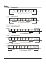
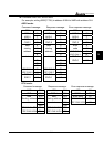
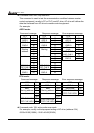
3.3 CMD (command code) and DATA (data character)
The format of data characters depends on the command code. The available
command codes are described as followed: