


VFD-F Series
DELTA ELECTRONICS, INC. ALL RIGHTS RESERVED
3-6
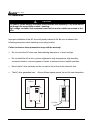
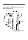
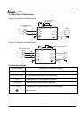
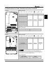
3.3 Main Circuit Connection
Figure 1 for the main circuit terminals
R(L1)
S(L2)
T(L3)
R
S
T
U(T1)
V(T2)
W(T3)
IM
3~
MC
E
E
+1 +2/B1
B2
-
Brake Resistor
(Optional)
Motor
Non-fuse breaker
(NFB)
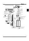
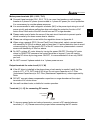
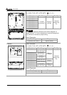
Figure 2 for the main circuit terminals
R(L1)
S(L2)
T(L3)
R
S
T
U(T1)
V(T2)
W(T3)
IM
3~
MC
E
E
VFDB
+1
+2
-
Brake Resistor (Optional)
Non-fuse breaker
(NFB)
Motor
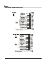
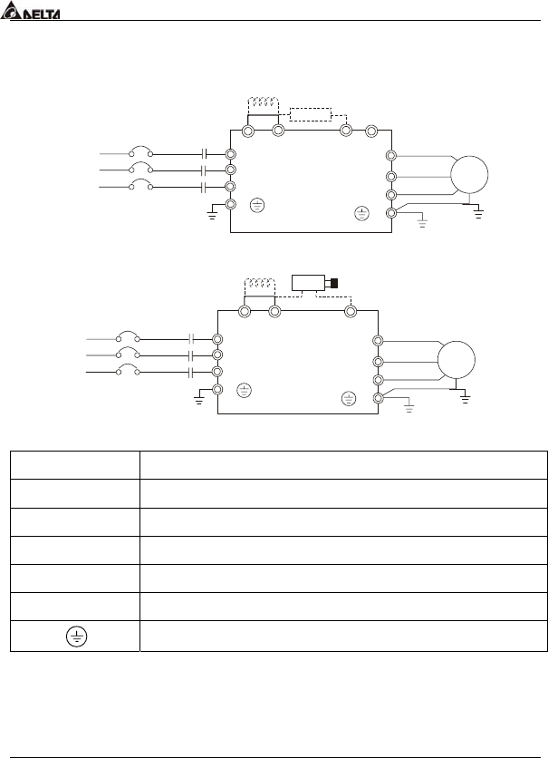
Terminal Explanations
Terminal Symbol Explanation of Terminal Function
R/L1, S/L2, T/L3 AC line input terminals
U/T1, V/T2, W/T3 AC drive output terminals motor connections
+1,+2 Connections for DC Link Reactor (optional)
+2/B1~B2 Connections for Brake Resistor (optional)
+2~ -,+2/B1~ - Connections for External Brake Unit (VFDB series)
Earth Ground