


VFD-F Series
DELTA ELECTRONICS, INC. ALL RIGHTS RESERVED
5-18
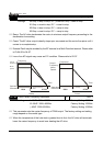
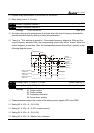
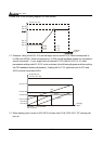
Setting 04: 0-10V = 0.0 - output power factor 1.0
When using 0-20mA output, please refer to Pr. 3-14.
Maximum impedance loading of analog output 2 (AFM2) can’t be greater than 500 ohms.
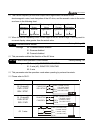
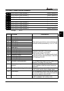
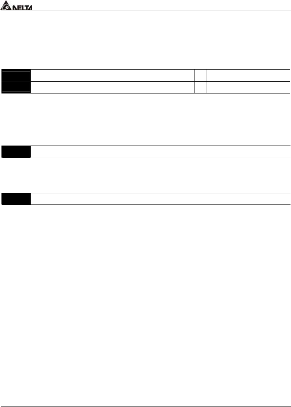
03 - 12 Analog Output Gain 1
a
Factory Setting: 100
03 - 13 Analog Output Gain 2
Factory Setting: 100
Settings 01~200%
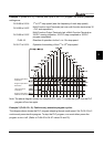
This parameter is to determine analog output gain.
The analog output is limited to 10V and 20mA. The gain is designed to offer a normally
small output signal to be enlarged for easier viewing on a meter.
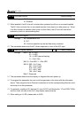
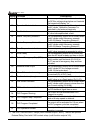
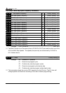
03 - 14 Analog Output 2 Selection
Factory Setting: 01
Settings
00: 0~20mA
01: 4~20mA
This parameter selects the output range of Analog Output 2 (AFM2).
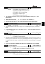
03 - 15 DC Fan Control
Factory Setting: 00
Settings
00: Fan runs on power up.
01: Fan begins upon a RUN command. Fan stops 1 minute after a
STOP command.
02: Fan begins upon a RUN command. Fan stops after a STOP
command
03: Fan is controlled by temperature. Approximately a 60°C
temperature will start the fan.
This parameter determines DC fan control method.