


VFD-F Series
DELTA ELECTRONICS, INC. ALL RIGHTS RESERVED
3-14
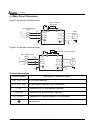
3.6 Wiring Notes:
PLEASE READ PRIOR TO INSTALLATION.
1.
!
CAUTION:
Do not connect the AC power to the U/T1, V/T2, W/T3 terminals, as it
will damage the AC drive.
2.
!
WARNING: Ensure all screws are tightened to the proper torque rating.
3. During installation, follow all local electrical, construction, and safety codes for the
country the drive is to be installed in.
4. Ensure that the appropriate protective devices (circuit breaker or fuses) are connected
between the power supply and AC drive.
5. Make sure that the leads are connected correctly and the AC drive is properly grounded.
(Ground resistance should not exceed 0.1
Ω
.)
6. Use ground leads that comply with AWG/MCM standards and keep them as short as
possible.
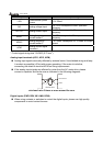
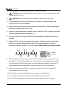
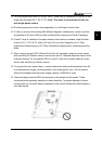
7. Multiple VFD-F units can be installed in one location. All the units should be grounded
directly to a common ground terminal. The VFD-F ground terminals may also be
connected in parallel, as shown in the figure below. Ensure there are no ground loops.
Forward
running
8. When the AC drive output terminals U/T1, V/T2, and W/T3 are connected to the motor
terminals U, V, and W, respectively, the motor will rotate counterclockwise (as viewed
from the shaft ends of the motor) when a forward operation command is received. To
reverse the direction of motor rotation, switch over any of the two motor leads.
9. Make sure that the power source is capable of supplying the correct voltage and
required current to the AC drive.
10. Do not attach or remove wiring when power is applied to the AC drive.
11. Do not inspect components unless inside “CHARGE” lamp is turned off.
12. Do not monitor the signals on the circuit board while the AC drive is in operation.