


5
VFD-F Series
DELTA ELECTRONICS, INC. ALL RIGHTS RESERVED
5-11
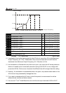
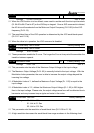
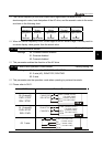
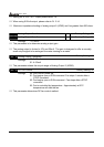
The Carrier frequency of the PWM output has a signification influence on the
electromagnetic noise, heat dissipation of the AC drive, and the acoustic noise to the motor
as shown in the following chart.
Carrier
frequency
Acoustic
Noise
Electromagnetic
Noise
Leakage
Current
Heat
Dissipation
Signification
Minimal
Minimal
Signification
Signification
Minimal
Signification
Minimal
Signification
Minimal
When the carrier frequency is low, current ripple of the AC drive is large. This may result in
a current display value greater than the actual value.
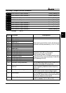
02 - 04 Forward/Reverse Enable
Factory Setting: 00
Settings 00: Forward/Reverse enabled
01: Reverse disabled
02: Forward disabled
This parameter enables the direction of the AC drive.
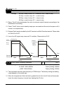
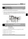
02 - 05 2-wire/3-wire Operation Control Modes
Factory Setting: 00
Settings 00: 2-wire (#1), FWD/STOP, REV/STOP
01: 2-wire (#2), RUN/STOP, REV/FWD
02: 3-wire
This parameter sets the operation mode when operating by external terminals.
Please refer to 02-01.
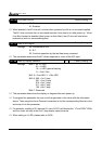
02-05 External Terminal
00 (2-wire #1)
FWD / STOP
REV / STOP
REV:
DCM
W
D
F
REV/STOP
FWD/STOP
:("OPEN":STOP)
("CLOSE":FWD)
("OPEN":STOP)
("CLOSE":REV)
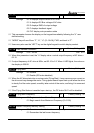
01 (2-wire #2)
RUN / STOP
REV / FWD
REV
DCM
W
D
F
FWD/REV
RUN/STOP
:("OPEN":STOP)
("CLOSE":RUN)
:("OPEN":FWD)
("CLOSE":REV)
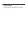
02 3-wire
REV
DCM
WDF
VFD-F
FWD/REV
STOP
("OPEN":STOP)
("OPEN":FWD)
("CLOSE":REV)
RUN
EF
("CLOSE":RUN)