


5
VFD-F Series
DELTA ELECTRONICS, INC. ALL RIGHTS RESERVED
5-63
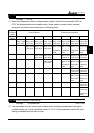
5.12 Group 11: Fan and Pump Control Parameters
11 - 00 V/f Curve Selection
Factory Setting: 00
Settings
00: Determined by group 1
01: 1.5 power curve
02: 1.7 power curve
03: 2 power curve
04: cube curve
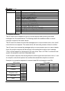
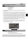
This parameter is to set V/f curve. If this parameter isn’t set to 00, parameter 01-03 and
01-04 will disable.
Input current of the motor could divide into two orthogonal vectors: magnetic vector and
torque vector. Gap flux, which is produced by Magnetic vector, is in direct proportion with
output voltage of motor. Torque vector produces torque. Torque is in direct proportion with
the result of magnetic vector multiply by torque vector. In theory, if the value of magnet
vector is the same with torque vector (in unsaturated flux condition), the input current is
minimum. If motor loading is unsteady torque loading (loading torque is in direct proportion
with speed. For example, the loading of fan or pump), loading torque is low during low
speed, suitable lower input voltage will decrease input current of magnetic field to lower flux
loss and iron loss of the motor and promote whole efficiency.
When this parameter is set to high power V/f curve and low frequency torque is lower, it is
not suitable for AC drive to accel/decel quickly. If it needs to accel/decel quickly, it is not
recommended to use this parameter.
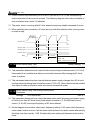
Frequency
%
02040
60
80
100
10
20
30
40
50
60
70
80
90
100
Voltage%
01-02
01-01
1.5 power curve
1.7 power curve
2 power curve
3 power curve
V/F Curve Diagram
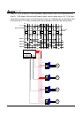
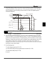
11 - 01 Circulative Control
Factory Setting: 00
Settings
00: No function
01: Time circulation (by time)
02: Fixed amount circulation (by PID)
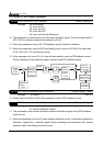
03: Fixed amount control (an AC drive runs with 4 motors)
This parameter is to set an AC drive runs with multiple motors in circulation control mode.