


5
VFD-F Series
DELTA ELECTRONICS, INC. ALL RIGHTS RESERVED
5-13
02 - 09 Special Display
a
Factory Setting: 00
Settings 00: A displays output current of AC drive
01: U displays DC-Bus voltage of AC drive
02: E displays RMS of output voltage
03: P displays feedback signal
04: PLC display auto procedure state
This parameter chooses the display on the keypad immediately following the “U” user
defined setting.
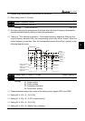
“MODE” key will scroll from “F”, “H”, “U”, (Pr. 02-09), FWD, and back to “F”.
Users may also use the “LEFT” key on the digital keypad to switch display content.
02 - 10 User Defined Coefficient
a
Factory Setting: 1.00
Settings 0.01~160.00 Unit: 0.01
When this parameter is set, the “H “display value = actual output frequency of AC drive x
02-10.
If output frequency of AC drive is 90Hz, set 02-10 to 2.5. When H LED lights, the value on
the display is 225.00.
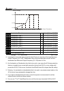
02 - 11 Flying Start
a
Factory Setting: 00
Settings 00: Disable
01: Enable (DC brake disabled)
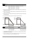
When the AC drive starts into a running motor (Flying Start), it may cause an over current on
the drive and may damage the motor. Using speed search upon start-up will allow the drive
to slowly find the motor speed, smoothly take control of the motor, and bring it to command
speed.
If the Flying Start feature is enabled upon start-up, the DC brake 08-01 will be disabled.
02 - 12 Flying Start Frequency
a
Factory Setting: 00
Settings 00: Begin search from Master Frequency Command
01: Begin search from Maximum Frequency (Pr.01-00)
02 - 13 Master Frequency Memory Setting
a
Factory Setting: 01
Settings 00: Do not remember the last known frequency
01: Remember the last known frequency