


VFD-F Series
DELTA ELECTRONICS, INC. ALL RIGHTS RESERVED
B-18
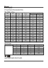
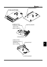
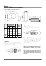
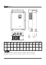
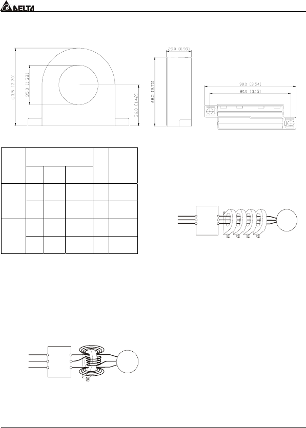
B.8 Zero Phase Reactor (RF220X00A)
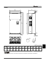
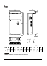
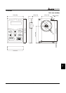
Dimensions are in millimeter and (inch)
Recommended
Wire Size (mm
2
)
Cable
type
(Note)
AWG mm
2
Nominal
(mm
2
)
Qty.
Wiring
Method
≦10 ≦5.3 ≦5.5
1
Diagram
A
Single-
core
≦2 ≦33.6 ≦38
4
Diagram
B
≦12 ≦3.3 ≦3.5
1
Diagram
A
Three-
core
≦1 ≦42.4 ≦50
4
Diagram
B
Note: 600V Insulated unshielded Cable.
Power
Supply
Zero Phase Reactor
MOTOR
U/T1
V/T2
W/T3
R/L1
S/L2
T/L3
U/T1
V/T2
W/T3
R/L1
S/L2
T/L3
Power
Supply
Zero Phase Reactor
MOTOR
Note 1:
The table above gives approximate
wire size for the zero phase reactors, but the
selection is ultimately governed by the type
and diameter of cable fitted, i.e. the cable
must fit through the center hole of zero
phase reactors.
Note 2: Only the phase conductors should
pass through, not the earth core or screen.
Note 3: When long motor output cables are
used, an output zero phase reactor may be
required to reduce radiated emissions from
the cable.
Diagram A
Please wind each wire 4 times around the
core. The reactor must be put at inverter
output as close as possible.
Diagram B
Please put all wires through 4 cores in
series without winding.