


VFD-F Series
DELTA ELECTRONICS, INC. ALL RIGHTS RESERVED
8-18
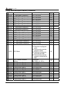
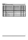
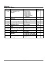
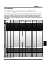
Group 10 PID Controls
Parameters Functions Settings
Factory
Setting
Customer
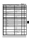
10-00 Input Terminal for PID
Feedback
00: No function
01: Input via AVI
02: Input via ACI1
03: Input via ACI2
04: Input via External
Reference
00
10-01 PID Control Detection Signal
Reference
0.0-6550.0 1000.0
10-02 PID Feedback Control Method 00: Negative feedback control
01: Positive feedback control
00
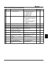
10-03 Proportional Gain (P) 0.0~10.0 1.0
10-04 Integral Time (I) 0.00~100.00 Sec 1.00
10-05 Differential Time (D) 0.00~1.00 Sec 0.00
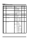
10-06 Upper Bound for Integral
Control
00~200% 100
10-07 Primary Low Pass Filter Time 0.0~2.5 Sec 0.0
10-08 PID Feedback Signal Range 0.0~6550.0 600.0
10-09 PID Feedback Signal Fault
Treatment Time
0. 0~3600.0 Sec
0.0: Disable
0.0
a
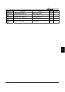
10-10 PID Feedback Signal Fault
Treatment
00: Warn and RAMP stop
01: Warn and COAST stop
02: Warn and keep operating
01
a
10-11 PID Minimum Output
Frequency
0: By PID controller
1: By AC drive
01