


VFD-F Series
DELTA ELECTRONICS, INC. ALL RIGHTS RESERVED
5-54
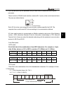
3.4 CHK (check sum)
ASCII mode:
LRC (Longitudinal Redundancy Check) is calculated by summing up, module 256,
the values of the bytes from ADR1 to last data character then calculating the
hexadecimal representation of the 2’s complement negation of the sum.
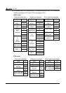
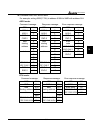
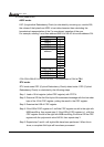
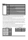
For example, reading 1 word from address 0401H of the AC drive with address 01H.
STX ‘:’
ADR 1 ‘0’
ADR 0 ‘1’
CMD 1 ‘0’
CMD 0 ‘3’
‘0’
‘4’
‘0’
Data starting
address
‘1’
‘0’
‘0’
‘0’
Number of data
‘1’
LRC CHK 1 ‘F’
LRC CHK 0 ‘6’
END 1 CR
END 0 LF
01H+03H+04H+01H+00H+01H=0AH, 2’s complement of 0AH is F6H.
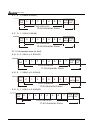
RTU mode:
RTU mode uses CRC (Cyclical Redundancy Check) detect value. CRC (Cyclical
Redundancy Check) is calculated by the following steps:
Step 1: Load a 16-bit register (called CRC register) with FFFFH.
Step 2: Excusive OR the first 8-bit byte of the command message with the low order
byte of the 16-bit CRC register, putting the result in the CRC register.
Step 3: Examine the LSB of CRC register.
Step 4: If the LSB of CRC register is 0, shift the CRC register one bit to the right with
MSB zerofilling, then repeat step 3. If the LSB of CRC register is 1, shift the
CRC register one bit to the right with MSB zerofilling, Exclusive OR the CRC
register with the polynomial value A001H, then repeat step 3.
Step 5: Repeat step 3 and 4 until eight shifts have been performed. When this is
done, a complete 8-bit byte will have been processed.