


5
VFD-F Series
DELTA ELECTRONICS, INC. ALL RIGHTS RESERVED
5-21
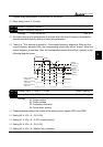
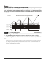
In noisy environments, it would be advantageous to verify the terminal status several times
before executing a new command, nearly eliminating false signals.
Example: If Pr.04-08 is set to 4, the AC drive will confirm the terminal status (4+1 = 5) 5
times before a change is made. This correlates to an 8~10msec time response from input
command to execution.
It is not recommended to set this parameter to 00, since interference may cause improper
operation of the AC drive.
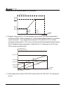
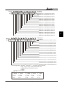
04 - 09 AVI Minimum Voltage
Factory Setting: 0.0
04 - 10 AVI Maximum Voltage
Factory Setting: 10.0
Settings 0.0 ~ 10.0V Unit: 0.1
04 - 11 AVI Minimum Frequency (percentage of Pr.1-00)
Factory Setting: 0.00
04 - 12 AVI Maximum Frequency (percentage of Pr.1-00)
Factory Setting: 100.00
Settings 0.00~100.00% Unit: 0.01
04 - 13 ACI1 Minimum Current
Factory Setting: 4.0
04 - 14 ACI1 Maximum Current
Factory Setting: 20.0
Settings 0.0 ~ 20.0mA Unit: 0.1
04 - 15 ACI1 Minimum Frequency (percentage of Pr.1-00)
Factory Setting: 0.00
04 - 16 ACI1 Maximum Frequency (percentage of Pr.1-00)
Factory Setting: 100.00
Settings 0.0~100.0% Unit: 0.01
04 - 17 ACI2 Minimum Current
Factory Setting: 4.0
04 - 18 ACI2 Maximum Current
Factory Setting: 20.0
Settings 0.0 ~ 20.0mA Unit: 0.1
04 - 19 ACI2 Minimum frequency (percentage of Pr.1-00)
Factory Setting: 0.00
04 - 20 ACI2 Maximum frequency (percentage of Pr.1-00)
Factory Setting: 100.00
Settings 0.00~100.00% Unit: 0.01
The above parameters are used to set the analog input reference values. The min and max
frequencies are based on Pr.01-00 (during open-loop control) or the PID reference value
Pr.10-01 (during PID close-loop control).