


VFD-F Series
DELTA ELECTRONICS, INC. ALL RIGHTS RESERVED
8-2
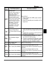
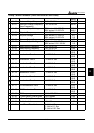
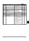
Parameters Functions Settings
Factory
Setting
Customer
00-02 AC Drive Status Indication 2 Bit 0~1: 00: Run led is off and stop
led is on.
01: Run led is blink and
stop led is on.
10: Run led is on and stop
led is blink.
11: Run led is on and stop
led is off.
Bit 2: 1: Jog on.
Bit 3~4: 00: Rev led is off and FWD
led is on.
01: Rev led is blink and
FWD led is on.
10: Rev led is on and
FWD led is blink.
11: Rev led is on and
FWD led is off.
Bit 5-7: Reserved
Bit 8: Master frequency source via
communication interface
Bit 9: Master frequency source via
analog
Bit10: Running command via
communication interface
Bit11: Parameter locked
Bit12~15: Reserved
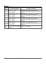
Read
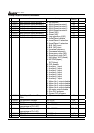
00-03 Frequency Setting Read only Read
00-04 Output Frequency Read only Read
00-05 Output Current Read only Read
00-06 DC-BUS Voltage Read only Read
00-07 Output Voltage Read only Read
00-08 Output Power Factor Read only Read
00- 09 Output Power (kW) Read only Read
00-10 Feedback Signal Actual
Value
Read only Read
00-11 Feedback Signal (%) Read only Read
00-12 User Target Value (Low bit)
uL 0-99.99
Read only Read
00-13 User Target Value (High bit)
uH 0-9999
Read only Read
00-14 PLC time Read only Read