


VFD-F Series
DELTA ELECTRONICS, INC. ALL RIGHTS RESERVED
5-10
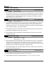
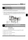
02 - 02 Stop Method
Factory Setting: 00
Settings 00:Stop = ramp to stop, E.F. (External Fault) = coast to stop
01:Stop = coast to stop, E.F. = coast to stop
02:Stop = ramp to stop, E.F. = ramp to stop
03:Stop = coast to stop, E.F. = ramp to stop
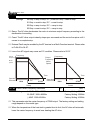
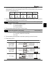
Ramp: The AC drive decelerates the motor to minimum output frequency according to the
deceleration time setting.
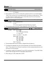
Coast: The AC drive output instantly stops upon command and the motor free spins until it
comes to a complete stop.
External Fault may be enabled by the EF terminal or a Multi-Function terminal. Please refer
to Pr.04-00 to 04-07.
Loss of an ACI signal may cause an E.F condition. Please refer to 02-07.
Motor
speed
Operation
Command
RUN
STOP
Stops according
to deceleration
time
Motor
Speed
Operation
Command
RUN
STOP
Free running
to stop
Frequency
Output
Frequency
Time
Frequency
Output
Frequency
Time
Ramp
Coast
02 - 03 PWM Carrier Frequency Selections
a
Unit: 1
Settings 1~10HP 4000~10000Hz Factory Setting: 9000Hz
15~30HP 3000~9000Hz Factory Setting: 6000Hz
≧40HP 2000~6000Hz
Factory Setting: 4000Hz
This parameter sets the carrier frequency of PWM output. The factory setting and setting
range depend on the model type.
When the temperature of the heat sink is greater than its limit, the AC drive will automatic
lower the carrier frequency to avoid over heating the AC drive.