


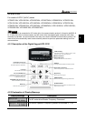

VFD-F Series
DELTA ELECTRONICS, INC. ALL RIGHTS RESERVED
5-2
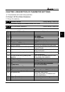
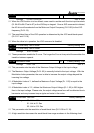
Code AC Drive Status Explanation
26 FAnP Fan Power Fault
27 FF1 Fan 1 Fault
28 FF2 Fan 2 Fault
29 FF3 Fan 3 Fault
30 FF123 Fan 1, 2, 3 Fault
31 FF12 Fan 1, 2 Fault
32 FF13 Fan 1, 3 Fault
33 FF23 Fan 2, 3 Fault
34 Fv Gate Drive Low Voltage Protect
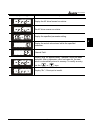
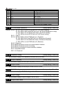
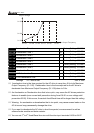
00 - 02 AC Drive Status Indication 2 Factory setting: Read Only
Display Bit 0~1: 00: Run LED is off and STOP led is on. (AC Drive stopping)
01: Run LED is blink and STOP led is on. (AC Drive deceleration to stop)
10: Run LED is on and STOP led is blink. (AC Drive standby)
11: Run LED is on and STOP led is off. (AC Drive running)
Bit 2: 1: Jog on.
Bit 3~4: 00: Rev LED is off and FWD led is on. (Forward)
01: Rev LED is blink and FWD led is on. (Reverse to Forward)
10: Rev LED is on and FWD led is blink. (Forward to Reverse)
11: Rev LED is on and FWD led is off. (Reverse)
Bit 5-7: Reserved
Bit 8: Master frequency source via communication interface
Bit 9: Master frequency source via analog
Bit10: Running command via communication interface
Bit11: Parameter locked
Bit12~15: Reserved
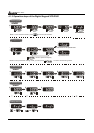
00 - 03 Frequency Setting Factory setting: Read Only
This parameter displays the frequency command set by the user.
00 - 04 Output Frequency Factory setting: Read Only
This parameter displays actual output frequency of the AC drive.
00 - 05 Output Current Factory setting: Read Only
This parameter displays actual output current of the AC drive.
00 - 06 DC-BUS Voltage Factory setting: Read Only
This parameter displays DC-BUS voltage of the AC drive.
00 - 07 Output Voltage Factory setting: Read Only
This parameter displays output voltage of the AC drive.
00 - 08 Output Power Factor Factory setting: Read Only