


VFD-F Series
DELTA ELECTRONICS, INC. ALL RIGHTS RESERVED
8-6
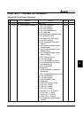
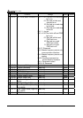
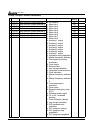
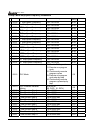
Group 3 Output Function Parameters
Parameters Functions Settings
Factory
Setting
Customer
03-00 Multi-function Output terminal 1 00
03-01 Multi-function Output terminal 2 00
03-02 Multi-function Output terminal 3 00
03-03 Multi-function Output terminal 4 00
03-04 Multi-function Output terminal 5 00
03-05 Multi-function Output terminal 6 00
03-06 Multi-function Output terminal 7 00
03-07 Multi-function Output terminal 8
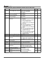
00: No function
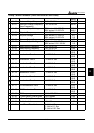
01: Motor No.1
02: Motor No.2
03: Motor No.3
04: Motor No.4
05: Motor No.5
06: Motor No.6
07: Motor No.7
08: Motor No.8
09: Auxiliary 1 output
10: Auxiliary 2 output
11: Auxiliary 3 output
12: Auxiliary 4 output
13: Auxiliary 5 output
14: Auxiliary 6 output
15: Auxiliary 7 output
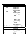
16: Indication during operation
17: Master frequency attained
18: Zero speed (including
shutdown)
19: Over-torque
20: External fault
21: Low voltage detection
22: Operation mode indication
23: Fault indication
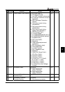
24: Master frequency attained
1
25: Master frequency attained
2
26: Over temperature
indication
27: Drive ready
28: External emergency stop
(EF1)
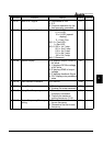
29: Software brake output
30: OL or OL1 overload
warning
31: Dwell indication (sleep)
32: Low current indication
33: PID feedback error
indication
34: PLC program running
35: PLC program step
completed
36: PLC program completed
00