


VFD-F Series
DELTA ELECTRONICS, INC. ALL RIGHTS RESERVED
3-10
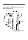
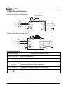
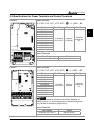
Terminal Symbols Terminal Functions Factory Settings
+10V
Potentiometer power
source
+10V 20mA
AVI Analog voltage Input
0 to +10V correspond to Max. operation
frequency
ACI 1/2 Analog current Input
4 to 20mA correspond to Max. operation
frequency
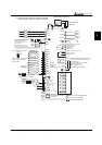
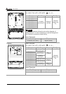
AFM 1
Analog frequency
/current meter 1
0 to 10V correspond to Max. operation
frequency
AFM 2
Analog frequency
/current meter 2
4 to 20mA correspond to 2 times of output
current
ACM
Analog control signal
(common)
* Control signal wiring size: 18 AWG (0.75 mm
2
).
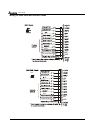
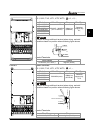
Analog input terminals (ACI1, ACI2, ACM)
Analog input signals are easily affected by external noise. Use shielded wiring and keep
it as short as possible (<20m) with proper grounding. If the noise is inductive,
connecting the shield to terminal ACM can bring improvement.
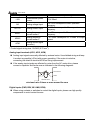
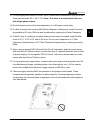
If the analog input signals are affected by noise from the AC motor drive, please
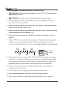
connect a capacitor and ferrite core as indicated in the following diagrams:
C
A
CI1/ACI2
ACM
ferrite core
wind each wire 3 times or more around the core
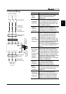
Digital inputs (FWD, REV, MI1~MI8, DCM)
When using contacts or switches to control the digital inputs, please use high quality
components to avoid contact bounce.