


5
VFD-F Series
DELTA ELECTRONICS, INC. ALL RIGHTS RESERVED
5-57
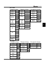
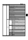
Content Address Function
14: Under voltage (Lv)
15: EEPROM WRITE failure (cF1)
16: EEPROM READ failure (cF2)
17: Base Block (bb)
18: Motor over load (oL2)
19: Reserved
20: Software or password protection (codE)
21: External emergency stop (EF1)
22: Phase-Loss (PHL)
23: Low current (Lc)
24: Feedback loss (FbL)
25: Reserved
26: FAnP (Fan Power Fault)
27: FF1 (Fan 1 Fault)
28: FF2 (Fan 2 Fault)
29: FF3 (Fan 3 Fault)
30: FF123 (Fan 1, 2, 3 Fault)
31: FF1, 2 (Fan 1, 2 Fault)
32: FF1, 3 (Fan 1, 3 Fault)
33: FF2, 3 (Fan 2, 3 Fault)
34: Gate Drive Low Voltage Protect (Fv)
Status of AC drive
00: Run LED is off and STOP led is on. (AC Drive
stopping)
01: RUN LED is blink and STOP led is on. (AC Drive
deceleration to stop)
10: RUN LED is on and STOP led is blink. (AC Drive
standby)
Bit 0-1
11: RUN LED is on and STOP led is off. (AC Drive
running)
Bit 2 Jog on
00: REV LED is off and FWD led is on. (Forward)
01: REV LED is blink and FWD led is on. (Reverse to
Forward)
10: REV LED is on and FWD led is blink. (Forward to
Reverse)
Bit 3~4
11: REV LED is on and FWD led is off. (Reverse)
Bit 5~7 Reserved
Bit 8 1: Master frequency source via communication
interface
Bit 9 1: Master frequency source via analog signal
Bit 10 1: Running command via communication interface
Bit 11 1: Parameter locked
Bit 12 Reserved
Bit 13 Reserved
2101H
Bit 14-15 Reserved